
Arduino UNO Traffic Light System with Countdown Display and Melody
View and Edit Project In Cirkit Designer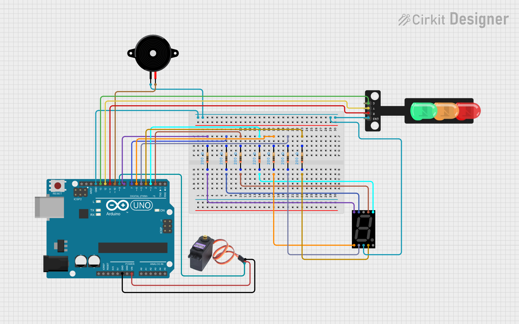
Circuit Documentation
Summary
This circuit is designed to control a traffic light system with a countdown display and a piezo speaker for sound alerts. The system is managed by an Arduino UNO microcontroller, which interfaces with a seven-segment display, a traffic light module, a piezo speaker, and a servo motor. The Arduino UNO runs a program that controls the traffic light sequence, displays countdown numbers on the seven-segment display, and plays a melody through the piezo speaker.
Component List
Arduino UNO
- Description: A microcontroller board based on the ATmega328P.
- Pins: UNUSED, IOREF, Reset, 3.3V, 5V, GND, Vin, A0, A1, A2, A3, A4, A5, SCL, SDA, AREF, D13, D12, D11, D10, D9, D8, D7, D6, D5, D4, D3, D2, D1, D0
Traffic Light
- Description: A module with three LEDs (Green, Yellow, Red) to simulate a traffic light.
- Pins: Green, Yellow, Red, GND
Piezo Speaker
- Description: A small speaker used to generate sound.
- Pins: pin1, pin2
MG996R Servo Motor
- Description: A high-torque servo motor.
- Pins: GND, VCC, SIG
Seven Segment Display (Wokwi Compatible)
- Description: A display module used to show numbers.
- Pins: G, F, COM.2, B, A, E, D, COM.1, C, DP
Resistors
- Description: Resistors used to limit current.
- Pins: pin1, pin2
- Properties:
- Resistance: 200 Ohms (6 instances)
- Resistance: 220 Ohms (1 instance)
Wiring Details
Arduino UNO
- D2: Connected to Resistor (200 Ohms) pin2, which is connected to Seven Segment Display pin A.
- D3: Connected to Resistor (200 Ohms) pin2, which is connected to Seven Segment Display pin B.
- D4: Connected to Resistor (200 Ohms) pin2, which is connected to Seven Segment Display pin C.
- D5: Connected to Resistor (200 Ohms) pin2, which is connected to Seven Segment Display pin D.
- D6: Connected to Resistor (200 Ohms) pin2, which is connected to Seven Segment Display pin E.
- D7: Connected to Resistor (200 Ohms) pin2, which is connected to Seven Segment Display pin F.
- D8: Connected to Resistor (200 Ohms) pin2, which is connected to Seven Segment Display pin G.
- D9: Connected to MG996R Servo Motor SIG pin.
- D10: Connected to Piezo Speaker pin2.
- D11: Connected to Traffic Light Red pin.
- D12: Connected to Traffic Light Yellow pin.
- D13: Connected to Traffic Light Green pin.
- Vin: Connected to MG996R Servo Motor VCC pin.
- GND: Connected to MG996R Servo Motor GND pin, Piezo Speaker pin1, Seven Segment Display COM.1 pin, and Traffic Light GND pin.
Traffic Light
- Green: Connected to Arduino UNO D13.
- Yellow: Connected to Arduino UNO D12.
- Red: Connected to Arduino UNO D11.
- GND: Connected to Arduino UNO GND.
Piezo Speaker
- pin1: Connected to Arduino UNO GND.
- pin2: Connected to Arduino UNO D10.
MG996R Servo Motor
- GND: Connected to Arduino UNO GND.
- VCC: Connected to Arduino UNO Vin.
- SIG: Connected to Arduino UNO D9.
Seven Segment Display (Wokwi Compatible)
- G: Connected to Resistor (200 Ohms) pin1, which is connected to Arduino UNO D8.
- F: Connected to Resistor (200 Ohms) pin1, which is connected to Arduino UNO D7.
- A: Connected to Resistor (200 Ohms) pin1, which is connected to Arduino UNO D2.
- B: Connected to Resistor (200 Ohms) pin1, which is connected to Arduino UNO D3.
- E: Connected to Resistor (200 Ohms) pin1, which is connected to Arduino UNO D6.
- D: Connected to Resistor (200 Ohms) pin1, which is connected to Arduino UNO D5.
- C: Connected to Resistor (200 Ohms) pin1, which is connected to Arduino UNO D4.
- COM.1: Connected to Arduino UNO GND.
Resistors
- 200 Ohms: Connected between Seven Segment Display pins (A, B, C, D, E, F, G) and Arduino UNO pins (D2, D3, D4, D5, D6, D7, D8).
- 220 Ohms: Connected between Seven Segment Display pin B and Arduino UNO D3.
Code Documentation
#include <Servo.h>      // Include the Servo library

Servo myServo;               // Create a Servo object

// Define 7-segment display pins
int segmentPins[] = {2, 3, 4, 5, 6, 7, 8}; // A, B, C, D, E, F, G

// Define the numbers to be displayed (0-9)
const byte numToSeg[10] =
{
  // A B C D E F G (segment ON = 1, OFF = 0)
  B00111111,  // 0
  B00000110,  // 1
  B01011011,  // 2
  B01001111,  // 3
  B01100110,  // 4
  B01101101,  // 5
  B01111101,  // 6
  B00000111,  // 7
  B01111111,  // 8
  B01000000,  // -
};

#define NOTE_A3  220
#define NOTE_B3  247
#define NOTE_G3  196

// notes in the melody:
int melody[] = {
  NOTE_B3, NOTE_A3, NOTE_G3, NOTE_A3, NOTE_B3
};

// note durations: 4 = quarter note, 8 = eighth note, etc.:
int noteDurations[] = {
  4, 8, 4, 8, 4
};

void playMelody()
{
  // Iterate over the notes of the melody:
  for (int thisNote = 0; thisNote < 5; thisNote++) {
    int noteDuration = 2000 / noteDurations[thisNote];
    tone(10, melody[thisNote], noteDuration); // Play melody on the buzzer (pin 10)
    int pauseBetweenNotes = noteDuration * 1.30;
    delay(pauseBetweenNotes);
    noTone(10); // Stop the tone
  }
}

void setup() {
  Serial.begin(9600);        // Initialize Serial communication

  // Set pins for 7-segment display as OUTPUT
  for (int i = 0; i < 7; i++) {
    pinMode(segmentPins[i], OUTPUT);
    digitalWrite(segmentPins[i], LOW);
  }

  pinMode(11, OUTPUT);       // RED light
  digitalWrite(11, LOW);      // Turn off red light

  pinMode(12, OUTPUT);       // Yellow light
  digitalWrite(12, LOW);      // Turn off yellow light

  pinMode(13, OUTPUT);       // GREEN light
  digitalWrite(13, LOW);      // Turn off yellow light

  pinMode(10, OUTPUT);       // Buzzer

  myServo.attach(9);         // Attach the servo to pin 9
  myServo.write(0);         // Set servo to remove the obstacle initially
}

void displayDigit(int digit)
{
  // Turn off all segments first to clear the display
  for (int i = 0; i < 7; i++) {
    digitalWrite(segmentPins[i], LOW);
  }

  // Get the segment pattern for the current digit
  byte segments = numToSeg[digit];

  // Turn on the correct segments based on the pattern
  for (int i = 0; i < 7; i++) {
    if (segments & (1 << i)) {
      digitalWrite(segmentPins[i], HIGH);  // Turn ON the segment
    }
  }
}

void loop() {

  // RED Light and Melody
  digitalWrite(11, HIGH);
  playMelody();               // Play melody before green light
  myServo.write(0); // Engage the obstacle (block