
Wi-Fi Controlled Smart Home System with Arduino UNO and Sensors
View and Edit Project In Cirkit Designer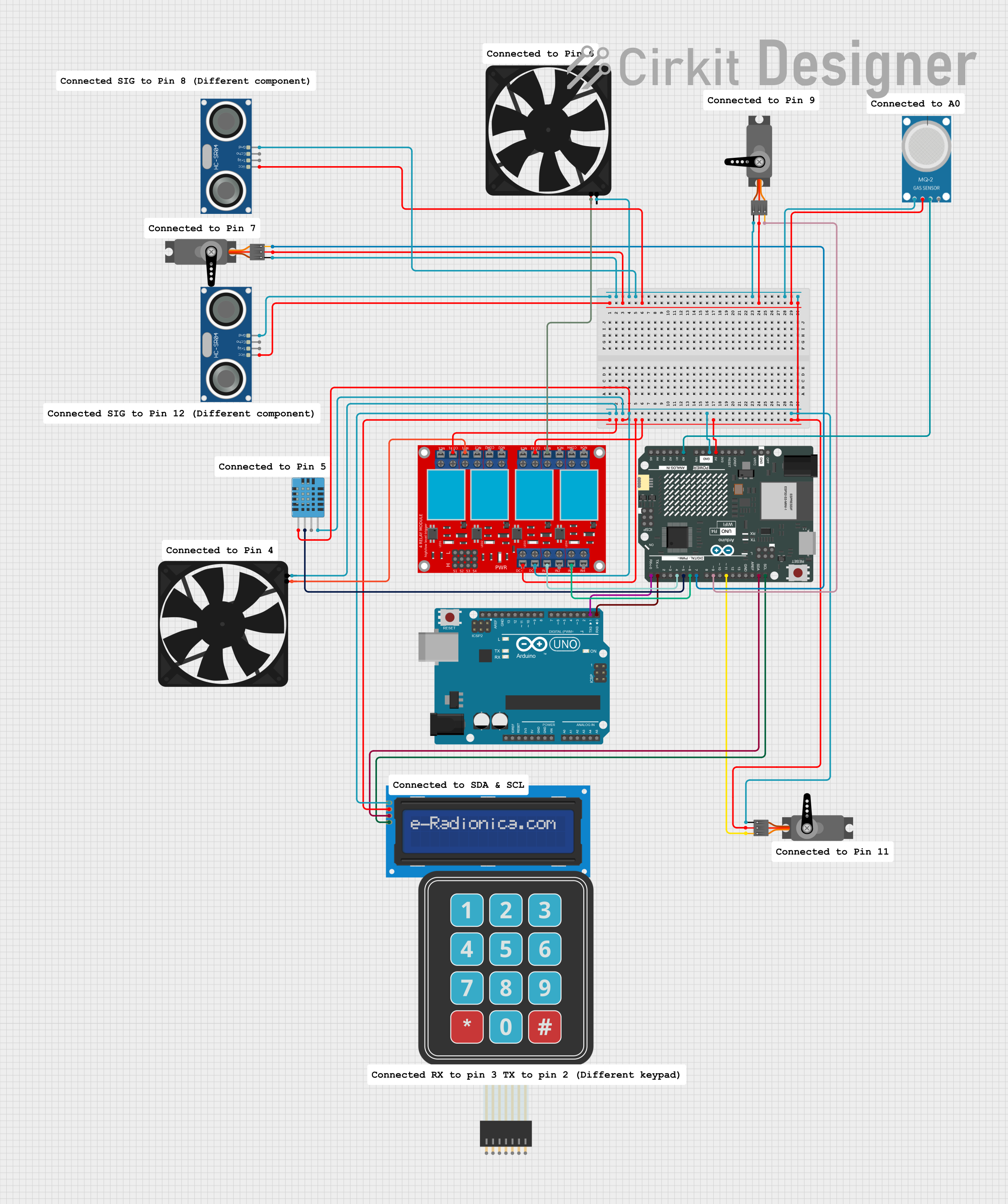
Circuit Documentation
Summary
This circuit involves an Arduino UNO R4 WiFi microcontroller, an Arduino UNO microcontroller, various sensors, servos, a relay module, and other components. The circuit is designed to control multiple devices, including a fan, servos, and an LCD screen, while also monitoring environmental conditions using sensors. The Arduino UNO R4 WiFi is the primary controller, handling most of the operations, while the Arduino UNO is used for additional functionalities.
Component List
Arduino UNO R4 WiFi
- Description: A microcontroller board based on the ATmega328P with built-in WiFi capabilities.
- Pins: OFF, GND, VRTC, IIC0_SCL, IIC0_SDA, 3V3, GPIO 41, GPIO 0, GPIO 42, GPIO 43, GPIO 44, BOOT, IOREF, RESET, 5V, VIN, A0, A1, A2, A3, A4, A5, RSPCKA, CIPO, COPI, D0/RX, D1/TX, D2, D3, D4, D5, D6, D7, D8, D9, D10, D11, D12, D13, AREF, SDA, SCL
LCD screen 16x2 I2C
- Description: A 16x2 character LCD display with I2C interface.
- Pins: SCL, SDA, VCC, GND
Membrane Matrix Keypad
- Description: A keypad with a matrix of buttons.
- Pins: Row 1, Row 2, Row 3, Row 4, Column 1, Column 2, Column 3
Arduino UNO
- Description: A microcontroller board based on the ATmega328P.
- Pins: UNUSED, IOREF, Reset, 3.3V, 5V, GND, Vin, A0, A1, A2, A3, A4, A5, SCL, SDA, AREF, D13, D12, D11, D10, D9, D8, D7, D6, D5, D4, D3, D2, D1, D0
4 channel relay module
- Description: A module with 4 relays for controlling high-power devices.
- Pins: N.O. 4, COM 4, N.C. 4, N.O. 3, COM 3, N.C. 3, N.O. 2, COM 2, N.C. 2, N.O. 1, COM 1, N.C. 1, Pin 13, Pin 14, Pin 15, Pin 16, Pin 17, Pin 18, Pin 19, Pin 20, Pin 21, Pin 22, Pin 23, Pin 24, VCC+, VCC- (GND), IN 1, IN 2, IN 3, IN 4
Servo
- Description: A servo motor for precise control of angular position.
- Pins: GND, VCC, PWM
Fan
- Description: A fan for cooling or ventilation.
- Pins: GND, 5V
HC-SR04 Ultrasonic Sensor
- Description: An ultrasonic sensor for distance measurement.
- Pins: VCC, TRIG, ECHO, GND
MQ-2
- Description: A gas sensor for detecting various gases.
- Pins: GND, VCC, ANALOG, Digital
DHT11 Humidity and Temperature Sensor
- Description: A sensor for measuring humidity and temperature.
- Pins: VDD, DATA, NULL, GND
Wiring Details
Arduino UNO R4 WiFi
- 5V: Connected to VCC of LCD screen 16x2 I2C, VCC+ of 4 channel relay module, VDD of DHT11 Humidity and Temperature Sensor, VCC of all Servos, VCC of both HC-SR04 Ultrasonic Sensors, and VCC of MQ-2.
- GND: Connected to GND of LCD screen 16x2 I2C, VCC- (GND) of 4 channel relay module, GND of DHT11 Humidity and Temperature Sensor, GND of all Servos, GND of both HC-SR04 Ultrasonic Sensors, GND of both Fans, and GND of MQ-2.
- A0: Connected to ANALOG of MQ-2.
- D0/RX: Connected to D1 of Arduino UNO.
- D1/TX: Connected to D0 of Arduino UNO.
- D4: Connected to IN 1 of 4 channel relay module.
- D5: Connected to DATA of DHT11 Humidity and Temperature Sensor.
- D6: Connected to IN 3 of 4 channel relay module.
- D7: Connected to PWM of one Servo.
- D9: Connected to PWM of another Servo.
- D11: Connected to PWM of another Servo.
- SDA: Connected to SDA of LCD screen 16x2 I2C.
- SCL: Connected to SCL of LCD screen 16x2 I2C.
LCD screen 16x2 I2C
- VCC: Connected to 5V of Arduino UNO R4 WiFi.
- GND: Connected to GND of Arduino UNO R4 WiFi.
- SDA: Connected to SDA of Arduino UNO R4 WiFi.
- SCL: Connected to SCL of Arduino UNO R4 WiFi.
Membrane Matrix Keypad
- No connections specified in the net list.
Arduino UNO
- D1: Connected to D0/RX of Arduino UNO R4 WiFi.
- D0: Connected to D1/TX of Arduino UNO R4 WiFi.
4 channel relay module
- VCC+: Connected to 5V of Arduino UNO R4 WiFi.
- VCC- (GND): Connected to GND of Arduino UNO R4 WiFi.
- IN 1: Connected to D4 of Arduino UNO R4 WiFi.
- IN 3: Connected to D6 of Arduino UNO R4 WiFi.
- COM 1: Connected to VCC of LCD screen 16x2 I2C.
- COM 3: Connected to VCC of LCD screen 16x2 I2C.
- N.O. 3: Connected to 5V of Fan.
- N.O. 1: Connected to 5V of another Fan.
Servo
- VCC: Connected to 5V of Arduino UNO R4 WiFi.
- GND: Connected to GND of Arduino UNO R4 WiFi.
- PWM: Connected to D7, D9, and D11 of Arduino UNO R4 WiFi.
Fan
- 5V: Connected to N.O. 3 and N.O. 1 of 4 channel relay module.
- GND: Connected to GND of Arduino UNO R4 WiFi.
HC-SR04 Ultrasonic Sensor
- VCC: Connected to 5V of Arduino UNO R4 WiFi.
- GND: Connected to GND of Arduino UNO R4 WiFi.
MQ-2
- VCC: Connected to 5V of Arduino UNO R4 WiFi.
- GND: Connected to GND of Arduino UNO R4 WiFi.
- ANALOG: Connected to A0 of Arduino UNO R4 WiFi.
DHT11 Humidity and Temperature Sensor
- VDD: Connected to 5V of Arduino UNO R4 WiFi.
- GND: Connected to GND of Arduino UNO R4 WiFi.
- DATA: Connected to D5 of Arduino UNO R4 WiFi.
Documented Code
Arduino UNO R4 WiFi Code
#define BLYNK_PRINT Serial

#define BLYNK_TEMPLATE_ID "TMPL6I9ijnAKh"
#define BLYNK_TEMPLATE_NAME "Arduino wifi"
#define BLYNK_AUTH_TOKEN "xoXNLvrwltbZ_meN02RTk5GW5kjVqWls"

#include <Wire.h>
#include <Servo.h>
#include <WiFiS3.h>
#include <BlynkSimpleWifi.h>
#include <DHT.h>
#include <SPI.h>

char ssid[] = "iPhone";
char pass[] = "Jasper98308021";
BlynkTimer timer;

Servo servo1;
Servo doorServo;
Servo servo3;
int servoPin1 = 9;
int servoPin2 = 11;
int servoPin3 = 7;
bool isLocked = true;

#define DHTPIN 5
#define DHTTYPE DHT11
DHT dht(DHTPIN, DHTTYPE);

#define SIG_PIN 12
#define THRESHOLD_DISTANCE 3

#define SIG_PIN2 8