
ESP32-Based Wi-Fi Controlled Smart LED Strip with RFID and Buzzer
View and Edit Project In Cirkit Designer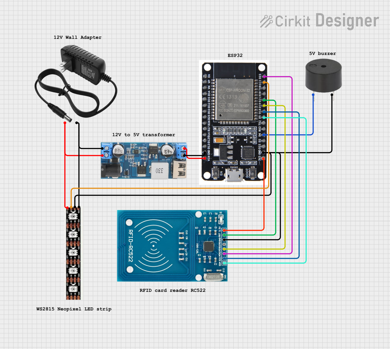
Circuit Documentation
Summary
This document provides a detailed overview of a circuit that includes an ESP32 microcontroller, a WS2815 LED strip, a 12V to 5V step-down power converter, a 12V power supply, an RFID-RC522 module, and a buzzer. The circuit is designed to control the LED strip and RFID module using the ESP32, with power management handled by the step-down converter and the 12V power supply.
Component List
ESP32
- Description: A powerful microcontroller with built-in Wi-Fi and Bluetooth capabilities.
- Pins: EN, VP, VN, D34, D35, D32, D33, D25, D26, D27, D14, D12, D13, GND, VIN, 3V3, D15, D2, D4, RX2, TX2, D5, D18, D19, D21, RX0, TX0, D22, D23, BOOT
WS2815 LED Strip
- Description: An addressable LED strip that operates at 12V.
- Pins: GND, B0, D0, +12V
12V to 5V Step Down Power Converter
- Description: A power converter that steps down 12V to 5V.
- Pins: VIN 9v-36v, VIN+, VIN-, USB OUTPUT 5V, 5v OUTPUT, GND
12V Power Supply
- Description: A power supply that provides 12V DC.
- Pins: +, -
RFID-RC522
- Description: An RFID module used for reading RFID tags.
- Pins: VCC (3.3V), RST, GND, IRQ, MISO, MOSI, SCK, SDA
Buzzer
- Description: A simple buzzer for audio output.
- Pins: PIN, GND
Wiring Details
ESP32
GND is connected to:
- GND of the 12V to 5V Step Down Power Converter
- GND of the Buzzer
- B0 of the WS2815 LED Strip
- GND of the RFID-RC522
VIN is connected to:
- 5V OUTPUT of the 12V to 5V Step Down Power Converter
3V3 is connected to:
- VCC (3.3V) of the RFID-RC522
D4 is connected to:
- PIN of the Buzzer
D5 is connected to:
- SDA of the RFID-RC522
D18 is connected to:
- SCK of the RFID-RC522
D19 is connected to:
- MISO of the RFID-RC522
D21 is connected to:
- RST of the RFID-RC522
D22 is connected to:
- D0 of the WS2815 LED Strip
D23 is connected to:
- MOSI of the RFID-RC522
WS2815 LED Strip
GND is connected to:
- VIN- of the 12V to 5V Step Down Power Converter
-
- of the 12V Power Supply
B0 is connected to:
- GND of the ESP32
D0 is connected to:
- D22 of the ESP32
+12V is connected to:
- VIN+ of the 12V to 5V Step Down Power Converter
-
- of the 12V Power Supply
12V to 5V Step Down Power Converter
GND is connected to:
- GND of the ESP32
5V OUTPUT is connected to:
- VIN of the ESP32
VIN- is connected to:
- GND of the WS2815 LED Strip
-
- of the 12V Power Supply
VIN+ is connected to:
- +12V of the WS2815 LED Strip
-
- of the 12V Power Supply
12V Power Supply
+ is connected to:
- VIN+ of the 12V to 5V Step Down Power Converter
- +12V of the WS2815 LED Strip
- is connected to:
- VIN- of the 12V to 5V Step Down Power Converter
- GND of the WS2815 LED Strip
RFID-RC522
VCC (3.3V) is connected to:
- 3V3 of the ESP32
GND is connected to:
- GND of the ESP32
SDA is connected to:
- D5 of the ESP32
SCK is connected to:
- D18 of the ESP32
MISO is connected to:
- D19 of the ESP32
MOSI is connected to:
- D23 of the ESP32
RST is connected to:
- D21 of the ESP32
Buzzer
PIN is connected to:
- D4 of the ESP32
GND is connected to:
- GND of the ESP32
Code
There is no code provided for this circuit.