Cirkit Designer
Your all-in-one circuit design IDE
Home /
Project Documentation
Arduino UNO Multi-Sensor Data Logger with RTC and SD Card Storage
Circuit Documentation
Summary
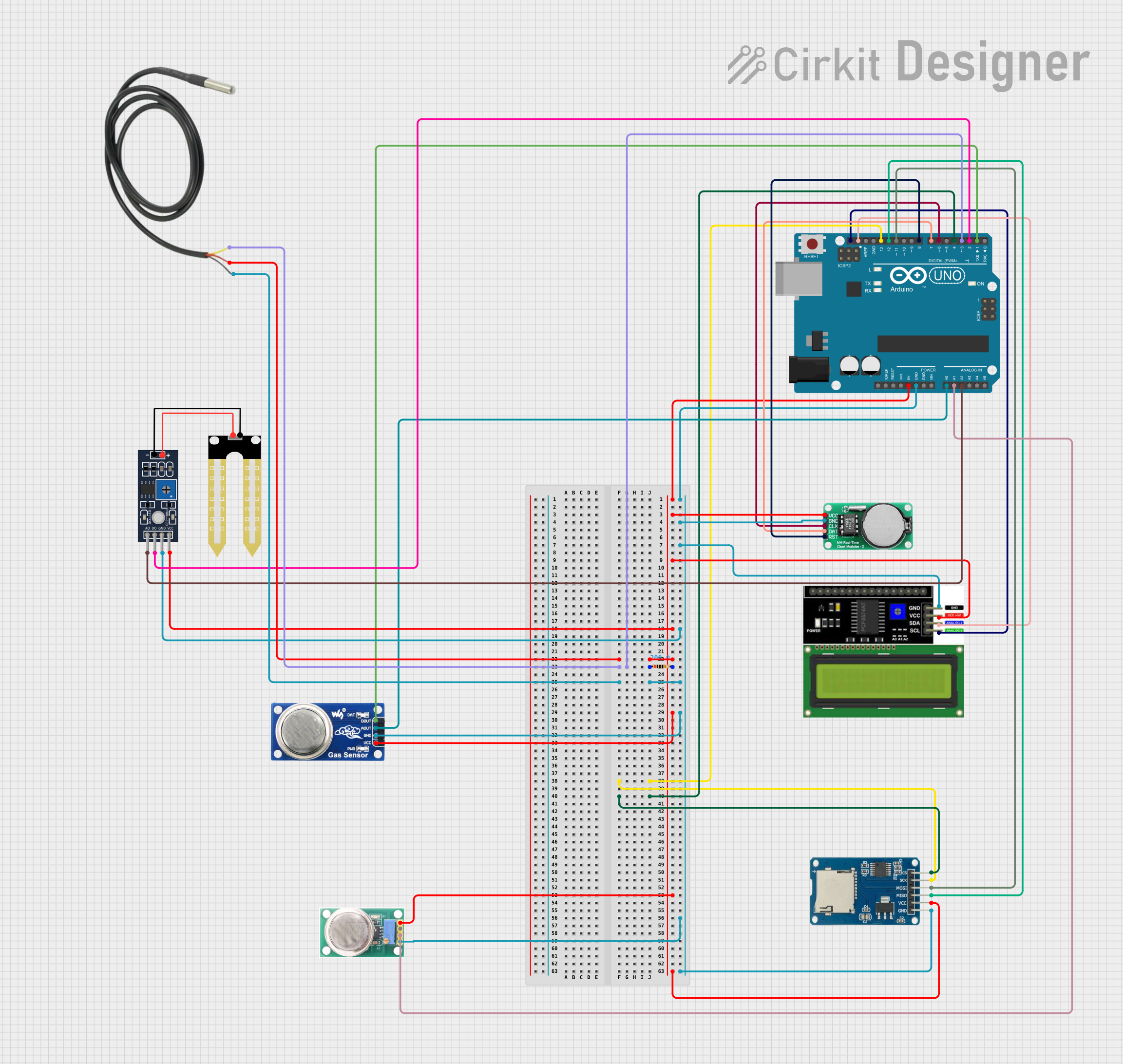
This circuit integrates various sensors and modules with an Arduino UNO microcontroller to perform a range of functions, including temperature sensing, humidity detection, gas level monitoring, real-time clock tracking, and data storage on a micro SD card. The circuit also features an LCD I2C display for output visualization. A resistor is used for pull-up configuration in the temperature sensor setup.
Component List
Arduino UNO
- Microcontroller board based on the ATmega328P
- It has 14 digital input/output pins, 6 analog inputs, a 16 MHz quartz crystal, a USB connection, a power jack, an ICSP header, and a reset button.
LCD I2C Display
- An alphanumeric liquid crystal display with an I2C interface for displaying data.
DS1302 RTC (Real-Time Clock)
- A real-time clock module for timekeeping purposes.
Micro SD Card Module
- A module that allows the Arduino to read from and write to micro SD cards.
MQ-136 Gas Sensor
- A hydrogen sulfide gas sensor for detecting H2S levels in the air.
MQ6 Gas Sensor
- A gas sensor for detecting LPG, butane, propane, methane, alcohol, hydrogen, and smoke.
Humidity Sensor YL-69
- A soil moisture sensor that can also be used to detect soil humidity levels.
Temperature Sensor
- A digital temperature sensor for measuring ambient temperature.
Resistor
- A 200 Ohm resistor used for the temperature sensor's pull-up configuration.
Wiring Details
Arduino UNO
5Vconnected to the VCC pins of the Temperature Sensor, DS1302 RTC, LCD I2C Display, Humidity YL-69, MQ6, MQ-136, and Micro SD Card Module.GNDconnected to the GND pins of the Temperature Sensor, DS1302 RTC, LCD I2C Display, Humidity YL-69, MQ6, MQ-136, and Micro SD Card Module.D3connected to the Resistor (pin1) and Temperature Sensor (Temp DQ Data Yellow).D4connected to the Micro SD Card Module (cs).D6connected to the DS1302 RTC (CLK).D7connected to the DS1302 RTC (DATA).D8connected to the DS1302 RTC (RST).D11connected to the Micro SD Card Module (mosi).D12connected to the Micro SD Card Module (miso).D13connected to the Micro SD Card Module (sck).A0connected to the MQ6 (A0).A1connected to the MQ-136 (OUT1).A2connected to the Humidity YL-69 (A0).SDAconnected to the LCD I2C Display (SDA).SCLconnected to the LCD I2C Display (SCL).D1connected to the MQ6 (DO).D2connected to the Humidity YL-69 (D0).
LCD I2C Display
GNDandVCCconnected to the common GND and 5V rails, respectively.SDAandSCLconnected to the corresponding SDA and SCL pins on the Arduino UNO.
DS1302 RTC
VCCandGNDconnected to the common 5V and GND rails, respectively.CLK,DATA, andRSTconnected to digital pins D6, D7, and D8 on the Arduino UNO, respectively.
Micro SD Card Module
vccandgndconnected to the common 5V and GND rails, respectively.cs,sck,mosi, andmisoconnected to digital pins D4, D13, D11, and D12 on the Arduino UNO, respectively.
MQ-136 Gas Sensor
VCCandGNDconnected to the common 5V and GND rails, respectively.OUT1connected to analog pin A1 on the Arduino UNO.
MQ6 Gas Sensor
VCCandGNDconnected to the common 5V and GND rails, respectively.A0connected to analog pin A0 on the Arduino UNO.DOconnected to digital pin D1 on the Arduino UNO.
Humidity Sensor YL-69
VCCandGNDconnected to the common 5V and GND rails, respectively.A0connected to analog pin A2 on the Arduino UNO.D0connected to digital pin D2 on the Arduino UNO.
Temperature Sensor
Temp VDD Redconnected to the common 5V rail through a 200 Ohm Resistor.Temp GND Blackconnected to the common GND rail.Temp DQ Data Yellowconnected to digital pin D3 on the Arduino UNO.
Resistor
pin1connected to digital pin D3 on the Arduino UNO.pin2connected to theTemp VDD Redpin of the Temperature Sensor.
Documented Code
Arduino UNO Code (sketch.ino)
void setup() {
  // put your setup code here, to run once:

}

void loop() {
  // put your main code here, to run repeatedly:

}
Note: The provided code is a template and does not include specific functionality. It needs to be populated with the logic to initialize and read from the connected sensors and modules, and to display data on the LCD I2C Display.