
Circuit Documentation
Summary
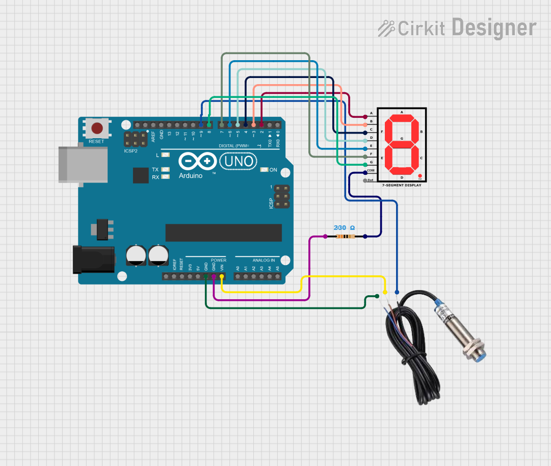
This circuit involves an Arduino UNO microcontroller interfacing with a 7-segment display, two inductive sensors, and two resistors. The Arduino UNO controls the 7-segment display and reads signals from the inductive sensors. The resistors are used to limit current in the circuit.
Component List
Inductive Sensor
- Pins: Signal, VCC, GND
- Description: Detects the presence of metallic objects.
- Properties: None
7-segment Display
- Pins: A, B, C, D, E, F, G, COM, dot
- Description: Displays numerical digits.
- Properties: None
Resistor (200 Ohms)
- Pins: pin1, pin2
- Description: Limits current in the circuit.
- Properties:
- Resistance: 200 Ohms
Resistor (330 Ohms)
- Pins: pin1, pin2
- Description: Limits current in the circuit.
- Properties:
- Resistance: 330 Ohms
Arduino UNO
- Pins: UNUSED, IOREF, Reset, 3.3V, 5V, GND, Vin, A0, A1, A2, A3, A4, A5, SCL, SDA, AREF, D13, D12, D11, D10, D9, D8, D7, D6, D5, D4, D3, D2, D1, D0
- Description: Microcontroller board used for interfacing and control.
- Properties: None
Wiring Details
Inductive Sensor 1
- Signal connected to Arduino UNO D9
- VCC connected to Arduino UNO Vin
- GND connected to Arduino UNO GND
Inductive Sensor 2
- Signal not connected
- VCC not connected
- GND not connected
7-segment Display
- A connected to Arduino UNO D2
- B connected to Arduino UNO D3
- C connected to Arduino UNO D4
- D connected to Arduino UNO D5
- E connected to Arduino UNO D6
- F connected to Arduino UNO D7
- G connected to Arduino UNO D8
- COM connected to Resistor (330 Ohms) pin2
- dot not connected
Resistor (200 Ohms)
- pin1 not connected
- pin2 not connected
Resistor (330 Ohms)
- pin1 connected to Arduino UNO GND
- pin2 connected to 7-segment Display COM
Arduino UNO
- D2 connected to 7-segment Display A
- D3 connected to 7-segment Display B
- D4 connected to 7-segment Display C
- D5 connected to 7-segment Display D
- D6 connected to 7-segment Display E
- D7 connected to 7-segment Display F
- D8 connected to 7-segment Display G
- D9 connected to Inductive Sensor 1 Signal
- Vin connected to Inductive Sensor 1 VCC
- GND connected to Inductive Sensor 1 GND
- GND connected to Resistor (330 Ohms) pin1
Documented Code
Arduino UNO 1
File Name: sketch.ino
void setup() {
  // put your setup code here, to run once:

}

void loop() {
  // put your main code here, to run repeatedly:

}
File Name: documentation.txt
Arduino UNO 2
File Name: sketch.ino
void setup() {
  // put your setup code here, to run once:

}

void loop() {
  // put your main code here, to run repeatedly:

}
File Name: documentation.txt