
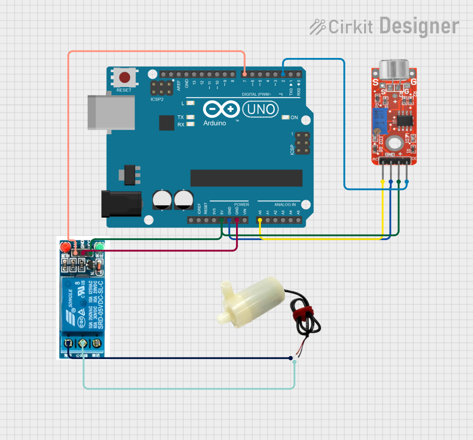
Circuit Documentation
Summary of the Circuit
This circuit is designed to activate a 5V mini water pump when a sound is detected by the KY-037 Microphone sensor. The Arduino UNO serves as the central controller, reading the digital output from the microphone sensor and controlling the 5V relay, which in turn powers the water pump. The system is powered by the 5V output from the Arduino UNO, which is shared with the microphone sensor and the relay module.
Component List
Arduino UNO
- Description: A microcontroller board based on the ATmega328P.
- Purpose: Acts as the central processing unit of the circuit, reading sensor inputs and controlling the relay.
KY-037 Microphone
- Description: A sound detection sensor module with both analog and digital outputs.
- Purpose: Detects sound levels in the environment and provides a digital signal to the Arduino when a threshold is exceeded.
5V Relay
- Description: An electromechanical switch that allows a low-power signal to control a higher power circuit.
- Purpose: Controls the power to the water pump based on the command from the Arduino.
5V Mini Water Pump
- Description: A small pump that operates on 5V DC power.
- Purpose: Sprinkles water when activated by the relay.
Wiring Details
Arduino UNO
- 5V: Provides power to the KY-037 Microphone and the 5V relay.
- GND: Common ground for the circuit.
- A0: Not connected in this circuit.
- D2: Receives the digital output from the KY-037 Microphone.
- D7: Controls the IN pin of the 5V relay.
KY-037 Microphone
- VCC: Connected to the 5V output of the Arduino UNO.
- Ground: Connected to the ground (GND) of the Arduino UNO.
- Analog output: Not used in this circuit.
- Digital output: Connected to pin D2 of the Arduino UNO.
5V Relay
- VCC: Connected to the 5V output of the Arduino UNO.
- GND: Connected to the ground (GND) of the Arduino UNO.
- In: Controlled by pin D7 of the Arduino UNO.
- Common terminal: Connected to the negative pin of the 5V mini water pump.
- Normally Open: Connected to the positive pin of the 5V mini water pump.
- Normally Closed: Not used in this circuit.
5V Mini Water Pump
- Positive pin: Connected to the Normally Open pin of the 5V relay.
- Negative pin: Connected to the Common terminal of the 5V relay.
Documented Code
// sketch.ino
const int soundSensorPin = 2;  // Pin connected to the sound sensor
const int pumpRelayPin = 7;    // Pin connected to the relay controlling the water pump
int sensorThreshold = 500;     // Adjust this threshold based on your sensor sensitivity

void setup() {
  pinMode(soundSensorPin, INPUT);
  pinMode(pumpRelayPin, OUTPUT);
  Serial.begin(9600);
}

void loop() {
  int soundValue = digitalRead(soundSensorPin); // Read sound sensor value

  if (soundValue == HIGH) {  // If sound is detected (mobile alarm rings)
    digitalWrite(pumpRelayPin, HIGH);  // Activate water sprinkler
    Serial.println("Sound detected! Sprinkler activated.");
  } else {
    digitalWrite(pumpRelayPin, LOW);   // Turn off the sprinkler if no sound is detected
  }

  delay(1000);  // Adjust delay as needed
}
Note: The sensorThreshold variable is defined but not used in the provided code. The digital output from the KY-037 Microphone is directly read and used to control the relay. If the analog output is to be used, the sensorThreshold would be relevant for comparing the analog sensor value.