
ESP8266-Based Motion and Water Detection System with Servo Control and LED Indicators
View and Edit Project In Cirkit Designer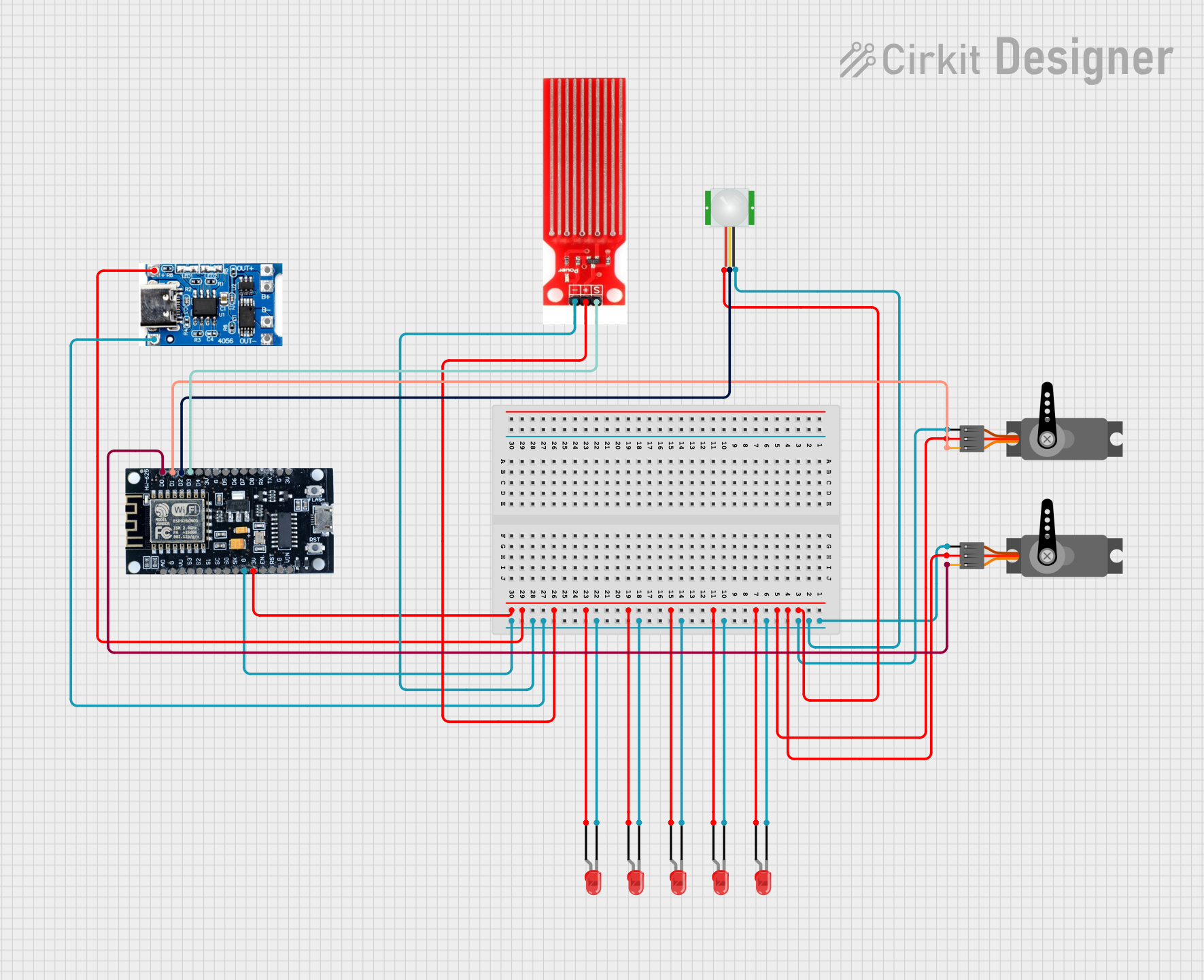
Circuit Documentation
Summary of the Circuit
This circuit is designed to interface an ESP8266 microcontroller with a variety of sensors and actuators, including a PIR sensor for motion detection, a water sensor for detecting the presence of water, two servo motors for mechanical movement, and multiple red LEDs for visual indication. The circuit also includes a TP4056 battery charging protection module to manage power delivery and charging. The ESP8266 serves as the central processing unit, controlling the servos based on inputs from the sensors and driving the LEDs.
Component List
ESP8266
- Description: A Wi-Fi capable microcontroller with multiple GPIO pins.
- Pins: 3V, G, D8, D7, D6, D5, D4, D3, D2, D1, D0, A0, S3, S2, S1, SC, S0, SK, EN, VIN, RST, VU
PIR Sensor
- Description: A passive infrared sensor that detects motion by measuring changes in the infrared levels emitted by surrounding objects.
- Pins: VDD, SIG, GND
Servo (x2)
- Description: An actuator capable of precise angular positioning, commonly used for steering mechanisms in robotics and RC vehicles.
- Pins: GND, VCC, PWM
Water Sensor
- Description: A sensor that detects the presence of water through electrical conductivity.
- Pins: Signal, VCC, GND
TP4056 Battery Charging Protection Module (Type C)
- Description: A module used for charging lithium batteries and protecting the circuit from overcharging.
- Pins: OUT +, B+, B-, OUT -, +, -
LED: Two Pin (red) (x5)
- Description: A basic red light-emitting diode used for indication purposes.
- Pins: cathode, anode
Wiring Details
ESP8266
- D3 connected to Water Sensor Signal
- D2 connected to PIR Sensor SIG
- D1 connected to Servo (1st instance) PWM
- D0 connected to Servo (2nd instance) PWM
- G (Ground) connected to the ground pins of all components
- 3V connected to the VCC/VDD pins of all components
PIR Sensor
- SIG connected to ESP8266 D2
- VDD connected to ESP8266 3V
- GND connected to ESP8266 G
Servo (1st instance)
- PWM connected to ESP8266 D1
- VCC connected to ESP8266 3V
- GND connected to ESP8266 G
Servo (2nd instance)
- PWM connected to ESP8266 D0
- VCC connected to ESP8266 3V
- GND connected to ESP8266 G
Water Sensor
- Signal connected to ESP8266 D3
- VCC connected to ESP8266 3V
- GND connected to ESP8266 G
TP4056 Battery Charging Protection Module (Type C)
-
- connected to ESP8266 3V
-
- connected to ESP8266 G
LED: Two Pin (red) (x5)
- anode connected to ESP8266 3V
- cathode connected to ESP8266 G
Documented Code
No code has been provided for the microcontroller. The documentation of the code would typically include a description of the functionality, setup, and main loop, along with comments explaining the purpose of each section of the code. Since no code is available, this section is left blank.