Cirkit Designer
Your all-in-one circuit design IDE
Home /
Project Documentation
Resistor Measurement Setup with Digital Multimeter and DC Power Supply

Circuit Documentation
Summary of the Circuit
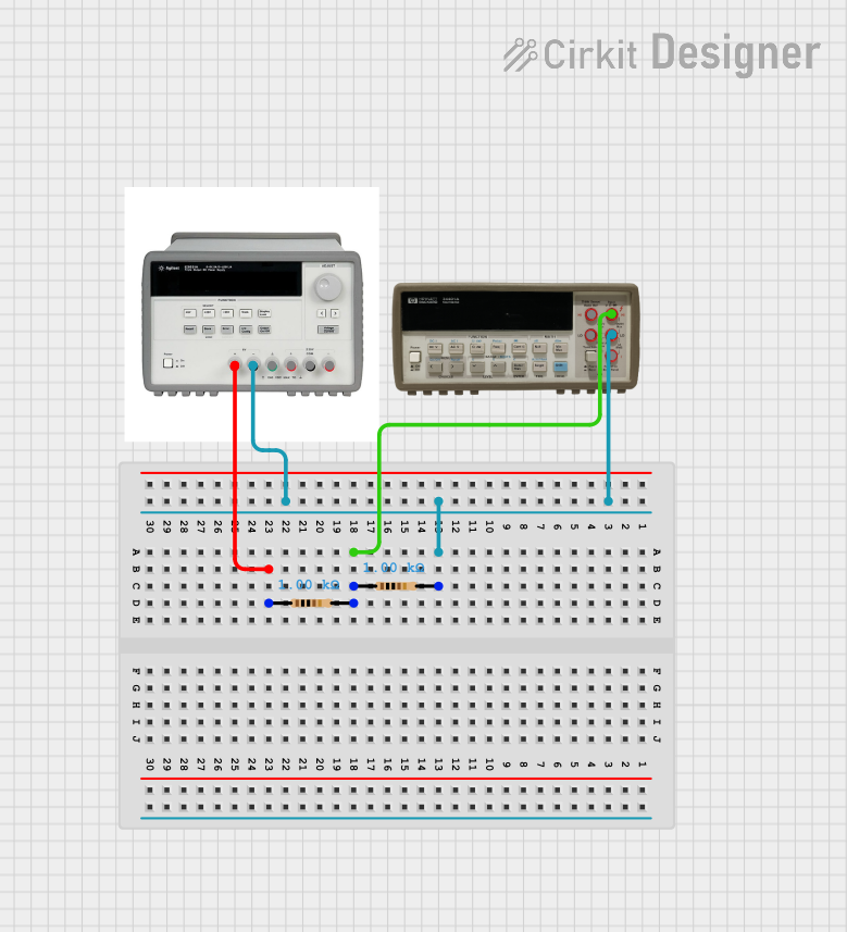
This circuit consists of two resistors, a triple output DC power supply, and a digital multimeter. The resistors are connected in series with the power supply and the multimeter to form a simple measurement setup. The power supply provides a 6V potential difference across the series combination of resistors, and the multimeter is used to measure the voltage or current through the resistors.
Component List
Resistor
- Description: A passive two-terminal electrical component that implements electrical resistance as a circuit element.
- Purpose: To limit the current flow and to divide voltages in the circuit.
- Properties:
- Resistance: 1000 Ohms
Triple Output DC Power Supply
- Description: A power supply unit that provides multiple DC voltage outputs.
- Purpose: To provide the necessary DC voltage to the circuit.
- Properties:
- Outputs: 6V and 25V lines
Digital Multimeter
- Description: An instrument designed to measure electric current, voltage, and usually resistance, typically over several ranges of value.
- Purpose: To measure the voltage across or current through the resistors.
- Properties:
- Measurement capabilities: Voltage, Current, Resistance
Wiring Details
Resistor 1
- Connections:
- One end connected to the 6V + output of the Triple Output DC Power Supply.
- The other end connected to one end of Resistor 2.
Resistor 2
- Connections:
- One end connected to the other end of Resistor 1.
- The other end connected to the 6V - output of the Triple Output DC Power Supply and the LO input of the Digital Multimeter.
Triple Output DC Power Supply
- Connections:
- 6V + output connected to one end of Resistor 1.
- 6V - output connected to one end of Resistor 2 and the LO input of the Digital Multimeter.
- GND, 25V +, 25V COM, and 25V - outputs are not connected in this circuit.
Digital Multimeter
- Connections:
- HI input connected to the junction between Resistor 1 and Resistor 2.
- LO input connected to the 6V - output of the Triple Output DC Power Supply and one end of Resistor 2.
- I input is not connected in this circuit.
Documented Code
There is no embedded code provided for any microcontrollers in this circuit. Therefore, this section is not applicable to the current documentation.