
Arduino UNO and SIM900A Based Smart Home Automation with GSM and I2C LCD Display
View and Edit Project In Cirkit Designer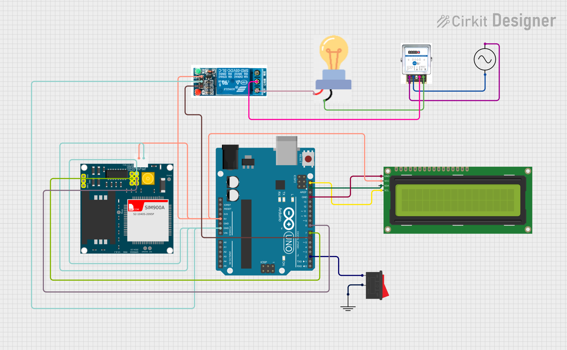
Circuit Documentation
Summary
This circuit involves an Arduino UNO microcontroller interfacing with a SIM900A GSM module, a 5V relay, a 16x2 I2C LCD, a rocker switch, an analog meter, and a bulb. The circuit is designed to control the bulb using the relay, display information on the LCD, and communicate via the GSM module. The analog meter is used to measure the AC supply.
Component List
Arduino UNO
- Description: A microcontroller board based on the ATmega328P.
- Pins: UNUSED, IOREF, Reset, 3.3V, 5V, GND, Vin, A0, A1, A2, A3, A4, A5, SCL, SDA, AREF, D13, D12, D11, D10, D9, D8, D7, D6, D5, D4, D3, D2, D1, D0
SIM900A
- Description: A GSM module for communication over cellular networks.
- Pins: GND, DB9-3 (RXD), DB9-2 (TXD), 5V, 3VR, 5VR, 3VT, 5VT, VCC, Ring, RESTART, RESET, STATUS
5V Relay
- Description: An electromechanical switch used to control high voltage devices.
- Pins: Normally Open, Common terminal, Normally Closed, In, GND, VCC
16x2 I2C LCD
- Description: A 16x2 character LCD display with I2C interface.
- Pins: GND, VCC, SDA, SCL
Rocker Switch
- Description: A simple on/off switch.
- Pins: 1, 2
AC Supply
- Description: An AC power supply.
- Pins: +ve, -ve
Analog Meter
- Description: A meter to measure electrical parameters.
- Pins: in +, IN -, Out +, Out -
Bulb
- Description: A simple light bulb.
- Pins: GND, power
GND
- Description: Ground connection.
- Pins: GND
Wiring Details
Arduino UNO
5V connected to:
- 5V Relay (VCC)
- SIM900A (5V)
- 16x2 I2C LCD (VCC)
GND connected to:
- 5V Relay (GND)
- SIM900A (GND)
- 16x2 I2C LCD (GND)
SCL connected to:
- 16x2 I2C LCD (SCL)
SDA connected to:
- 16x2 I2C LCD (SDA)
D8 connected to:
- SIM900A (5VR)
D7 connected to:
- SIM900A (5VT)
D6 connected to:
- 5V Relay (In)
D2 connected to:
- Rocker Switch (1)
SIM900A
5V connected to:
- Arduino UNO (5V)
GND connected to:
- Arduino UNO (GND)
5VR connected to:
- Arduino UNO (D8)
5VT connected to:
- Arduino UNO (D7)
5V Relay
VCC connected to:
- Arduino UNO (5V)
GND connected to:
- Arduino UNO (GND)
In connected to:
- Arduino UNO (D6)
Normally Open connected to:
- Bulb (power)
Common terminal connected to:
- Analog Meter (Out +)
16x2 I2C LCD
VCC connected to:
- Arduino UNO (5V)
GND connected to:
- Arduino UNO (GND)
SCL connected to:
- Arduino UNO (SCL)
SDA connected to:
- Arduino UNO (SDA)
Rocker Switch
1 connected to:
- Arduino UNO (D2)
2 connected to:
- GND (GND)
Analog Meter
Out + connected to:
- 5V Relay (Common terminal)
in + connected to:
- AC Supply (+ve)
IN - connected to:
- AC Supply (-ve)
Out - connected to:
- Bulb (GND)
Bulb
power connected to:
- 5V Relay (Normally Open)
GND connected to:
- Analog Meter (Out -)
Code Documentation
Arduino UNO Code
#include <SoftwareSerial.h>

// Define the pins for the GSM module
SoftwareSerial gsm(10, 11); // RX, TX

void setup() {
  // Initialize the hardware serial port
  Serial.begin(9600);

  // Initialize the software serial port for GSM module
  gsm.begin(115200); // Ensure this baud rate matches the A7670C module's requirements
}

void loop() {
  // Check if data is available from the GSM module
  if (gsm.available()) {
    // Read data from GSM module and send it to the Serial Monitor
    Serial.write(gsm.read());
  }

  // Check if data is available from the Serial Monitor
  if (Serial.available()) {
    // Read data from Serial Monitor and send it to the GSM module
    gsm.write(Serial.read());
  }
}
This code initializes the Arduino UNO to communicate with the SIM900A GSM module using software serial communication. The data received from the GSM module is sent to the Serial Monitor and vice versa.