
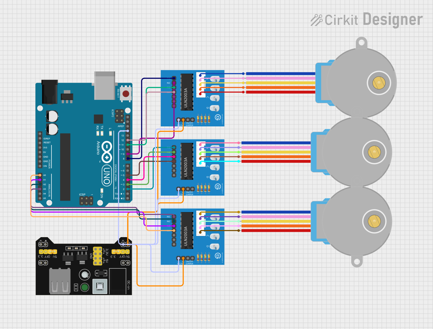
Circuit Documentation
Summary
This circuit primarily consists of an Arduino UNO microcontroller that is used to control multiple 28BYJ-48 Stepper Motors through ULN2003A breakout boards. The motors are driven by signals from the Arduino, which are amplified by the ULN2003A driver boards. A MB102 Breadboard Power Supply Module provides power to the system.
Component List
Arduino UNO
- Microcontroller board based on the ATmega328P
- It has 14 digital input/output pins, 6 analog inputs, a 16 MHz quartz crystal, a USB connection, a power jack, an ICSP header, and a reset button.
28BYJ-48 Stepper Motor (x3)
- A small, 5-volt geared stepping motor
- It has a stride angle of 5.625°/64 and can be used in various types of automation projects.
ULN2003A Breakout Board (x3)
- A board with a ULN2003A darlington transistor array, used for driving high-current loads.
- It has inputs for controlling the outputs, which are connected to the stepper motor.
MB102 Breadboard Power Supply Module 3.3V/5V
- A power supply module that can output a selectable 3.3V or 5V.
- It is used to power the breadboard and the components on it.
Wiring Details
Arduino UNO
A0toULN2003A breakout board In 4A1toULN2003A breakout board In 3A2toULN2003A breakout board In 2A3toULN2003A breakout board In 1GNDtoULN2003A breakout board 0V(Common Ground)D12toULN2003A breakout board In 4D11toULN2003A breakout board In 3D9toULN2003A breakout board In 2D8toULN2003A breakout board In 1D5toULN2003A breakout board In 4D4toULN2003A breakout board In 3D3toULN2003A breakout board In 2D2toULN2003A breakout board In 1
28BYJ-48 Stepper Motor
BLUEwire toULN2003A breakout board BLUE wirePINKwire toULN2003A breakout board PINK wireYELLOWwire toULN2003A breakout board YELLOW wireORANGEwire toULN2003A breakout board ORANGE wireREDwire toULN2003A breakout board RED wire
ULN2003A Breakout Board
In 1toArduino UNO D8/D2/A3In 2toArduino UNO D9/D3/A2In 3toArduino UNO D11/D4/A1In 4toArduino UNO D12/D5/A00VtoArduino UNO GND(Common Ground)+5VtoMB102 Breadboard Power Supply Module VCCON/OFF jumper switch(not connected)BLUE wireto28BYJ-48 Stepper Motor BLUEPINK wireto28BYJ-48 Stepper Motor PINKYELLOW wireto28BYJ-48 Stepper Motor YELLOWORANGE wireto28BYJ-48 Stepper Motor ORANGERED wireto28BYJ-48 Stepper Motor RED
MB102 Breadboard Power Supply Module 3.3V/5V
VCCtoULN2003A breakout board +5VGNDtoULN2003A breakout board 0V(Common Ground)
Documented Code
Arduino UNO Code (sketch.ino)
// Arduino stepper motor control code
#include <Stepper.h> // Include the header file
// change this to the number of steps on your motor
#define STEPS 32
// create an instance of the stepper class using the steps and pins
Stepper stepper(STEPS, 8, 9, 10, 11);
int val = 0;

void setup() {
    Serial.begin(9600);
    stepper.setSpeed(200);
}

void loop() {
    if (Serial.available()>0)
{
     val = Serial.parseInt();
     stepper.step(val);
     Serial.println(val); //for debugging
}
}
This code snippet is responsible for controlling the stepper motor via the Arduino UNO. It initializes the stepper motor with a specific number of steps and sets up the serial communication for debugging. The loop function listens for serial input to determine the number of steps the motor should take.
Additional Microcontroller Code
The additional microcontroller code provided is empty or contains only the default setup() and loop() functions without any operational code. Therefore, it is not included in this documentation.