
Arduino and ESP8266 Nodemcu Controlled Environmental Monitoring System
View and Edit Project In Cirkit Designer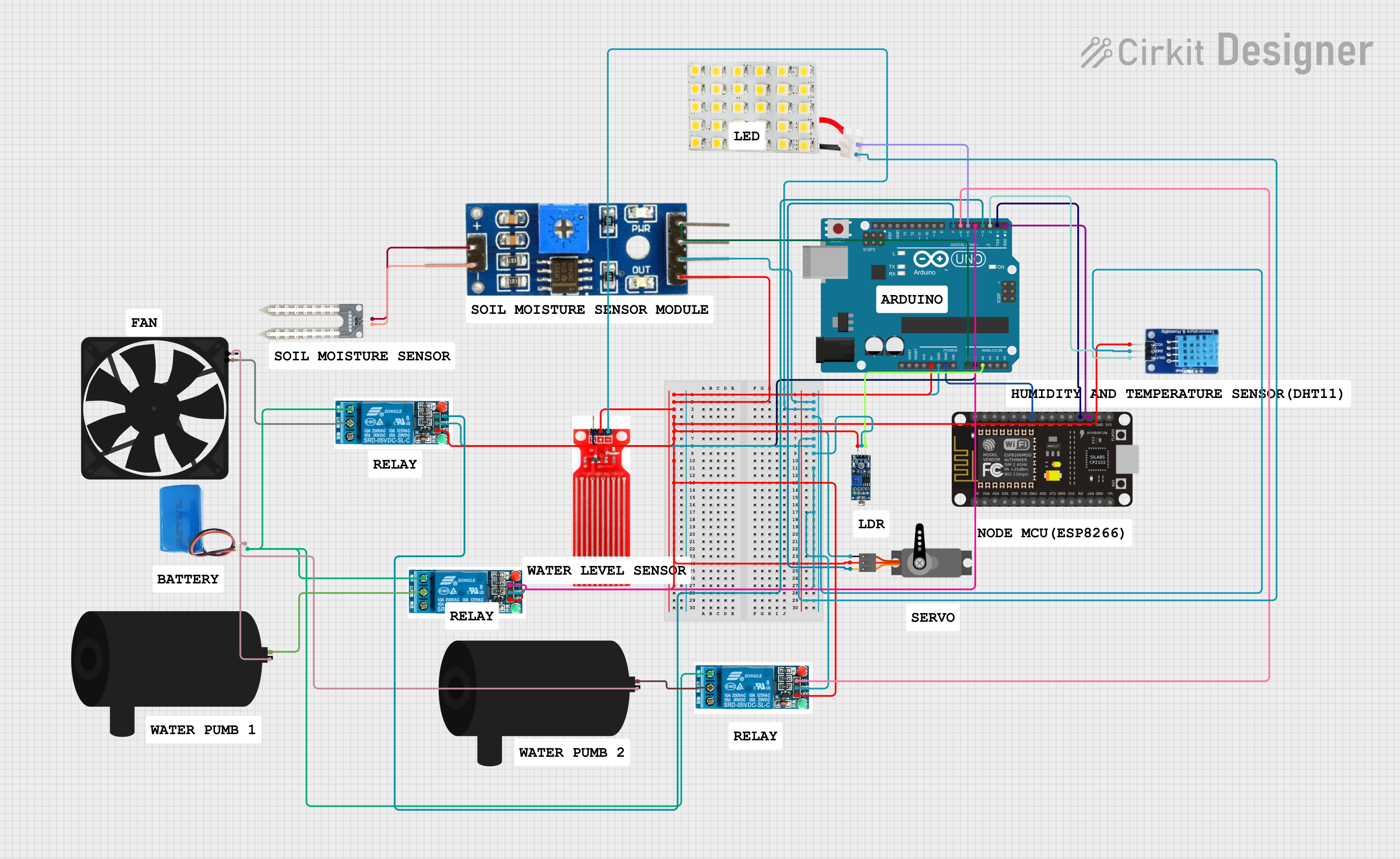
Circuit Documentation
Summary
The circuit in question appears to be a sensor and actuator network controlled by an Arduino UNO and an ESP8266 NodeMCU microcontroller. The circuit includes various sensors such as a DHT11 temperature and humidity sensor, a water sensor, a soil moisture module, and an LDR module for light detection. Actuators in the circuit include water pumps, a fan, and a servo motor. Additionally, there are multiple 5V relays to control the actuators and a 5V battery to provide power. The circuit is designed to interface the physical environment with the microcontrollers, which can be programmed to react to sensor inputs and control the actuators accordingly.
Component List
Microcontrollers
- ESP8266 NodeMCU: A Wi-Fi enabled microcontroller with multiple digital and analog pins.
- Arduino UNO: A microcontroller board based on the ATmega328P with digital and analog I/O pins.
Sensors
- DHT11: A sensor for measuring temperature and humidity.
- Water Sensor: A device for detecting the presence of water.
- Soil Moisture Module: A sensor for measuring the moisture content in soil.
- LDR Module 3 pin: A light-dependent resistor module for measuring light intensity.
Actuators
- 5V Relay: An electrically operated switch that allows controlling high power devices with low power signals.
- Water Pump: A device used to move water from one place to another.
- Fan: An electric device that creates airflow.
- Servo: A rotary actuator that allows for precise control of angular position.
Power Supply
- 5V Battery: A power source for the circuit.
Indicators
- LED Board: A board with LEDs that can be used for status indication.
Wiring Details
Microcontrollers
ESP8266 NodeMCU
GNDconnected to Arduino UNOGNDRXconnected to Arduino UNOD1TXconnected to Arduino UNOD0
Arduino UNO
5Vpowers DHT11VCC, Water SensorVCC, Soil Moisture ModuleVCC, LDR ModuleVCC, all 5V RelaysVCC, and ServoVCCGNDconnected to DHT11GND, Water SensorGND, Soil Moisture ModuleGround, LDR ModuleGND, all 5V RelaysGND, LED BoardGND, and ServoGNDA0connected to Soil Moisture ModuleAnalogA1connected to Water SensorSignalA2connected to LDR ModuleDOD2connected to DHT11DATAD3toD7control the 5V Relays and ServoPWMD5connected to LED BoardVCC
Sensors
DHT11
DATAconnected to Arduino UNOD2
Water Sensor
Signalconnected to Arduino UNOA1
Soil Moisture Module
Analogconnected to Arduino UNOA0
LDR Module 3 pin
DOconnected to Arduino UNOA2
Actuators
5V Relays
Inpins controlled by Arduino UNOD3,D4,D6Common terminalconnected to water pumps and fanNormally Openconnected to 5V batterypositive
Water Pumps
positiveconnected to 5V relayCommon terminalnegativeconnected to 5V batterynegative
Fan
5Vconnected to 5V relayCommon terminalGNDconnected to 5V batterynegative
Servo
PWMcontrolled by Arduino UNOD7
Power Supply
- 5V Battery
positiveconnected to 5V relaysNormally Opennegativeconnected to water pumpsnegative, fanGND
Indicators
- LED Board
VCCcontrolled by Arduino UNOD5
Documented Code
Arduino UNO Code (sketch.ino)
void setup() {
  // put your setup code here, to run once:

}

void loop() {
  // put your main code here, to run repeatedly:

}
Note: The code provided for the Arduino UNO is a template with empty setup and loop functions. Actual functionality needs to be implemented based on the desired behavior of the circuit.
ESP8266 NodeMCU Code
No code was provided for the ESP8266 NodeMCU.
Note: To fully utilize the ESP8266 NodeMCU, code should be written and uploaded to the microcontroller to handle Wi-Fi connectivity and interaction with the Arduino UNO and other components.