Cirkit Designer
Your all-in-one circuit design IDE
Home /
Project Documentation
Arduino UNO LED Control with Resistor
Circuit Documentation
Summary
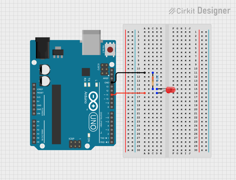
This circuit consists of an Arduino UNO microcontroller, a red LED, and a 220 Ohm resistor. The LED is connected to the Arduino UNO through the resistor, allowing the microcontroller to control the LED.
Component List
Arduino UNO
- Description: A microcontroller board based on the ATmega328P.
- Pins: UNUSED, IOREF, Reset, 3.3V, 5V, GND, Vin, A0, A1, A2, A3, A4, A5, SCL, SDA, AREF, D13, D12, D11, D10, D9, D8, D7, D6, D5, D4, D3, D2, D1, D0
- Purpose in Circuit: Acts as the main controller for the circuit.
LED: Two Pin (red)
- Description: A red light-emitting diode.
- Pins: cathode, anode
- Purpose in Circuit: Provides visual feedback by emitting light when powered.
Resistor
- Description: A 220 Ohm resistor.
- Pins: pin1, pin2
- Properties:
- Resistance: 220 Ohms
- Purpose in Circuit: Limits the current flowing through the LED to prevent damage.
Wiring Details
Arduino UNO
- GND: Connected to pin1 of the Resistor.
- D11: Connected to the anode of the LED.
LED: Two Pin (red)
- anode: Connected to D11 of the Arduino UNO.
- cathode: Connected to pin2 of the Resistor.
Resistor
- pin1: Connected to GND of the Arduino UNO.
- pin2: Connected to the cathode of the LED.
Documented Code
Arduino UNO Code
sketch.ino
void setup() {
  // put your setup code here, to run once:

}

void loop() {
  // put your main code here, to run repeatedly:

}
documentation.txt