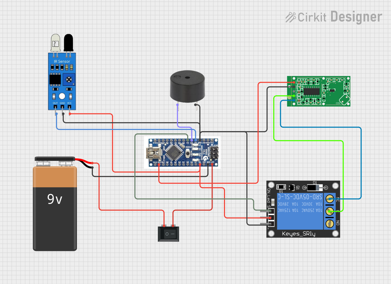
Arduino Nano-Based Motion Detection System with Audible Alert

Circuit Documentation
Summary of the Circuit
This circuit is designed to interface an Arduino Nano with various sensors and output devices, including an IR sensor, a microwave radar motion sensor module, a 1-channel relay, a buzzer, and a 9V battery with a rocker switch for power control. The Arduino Nano serves as the central processing unit, reading inputs from the sensors and controlling the relay and buzzer based on the sensor data. The relay can be used to switch higher power loads, and the buzzer provides audible feedback. The circuit is powered by a 9V battery, which is connected through a rocker switch to control the power supply to the circuit.
Component List
Arduino Nano
- Microcontroller board based on the ATmega328P
- Pins: D12, D11, D10, D9, D8, D7, D6, D5, D4, D3, D2, GND, RST, RX0, TX1, D13, 3V3, REF, A0, A1, A3, A4, A5, A6, A7, 5V, VIN
1-Channel Relay (5V 10A)
- Electromechanical switch with one normally closed (NC) and one normally open (NO) contact
- Pins: NC, signal, C, power, NO, ground
IR Sensor
- Sensor for detecting obstacles or motion based on infrared light
- Pins: out, gnd, vcc
RCWL-0516 Microwave Radar Motion Sensor Module
- Sensor for detecting motion through microwave radar technology
- Pins: CDS, VIN, OUT, GND, 3V3
9V Battery
- Standard 9V battery used as the power source for the circuit
- Pins: -, +
Buzzer
- An electromechanical component that produces sound
- Pins: PIN, GND
Rocker Switch (SPST)
- A single-pole single-throw (SPST) switch used to control the power supply
- Pins: 1, 2
Wiring Details
Arduino Nano
- D4 connected to 1-Channel Relay (signal)
- D3 connected to Buzzer (PIN)
- D2 connected to IR Sensor (out)
- GND connected to Buzzer (GND), 1-Channel Relay (ground), IR Sensor (gnd), RCWL-0516 Microwave Radar Motion Sensor Module (GND)
- 3V3 connected to RCWL-0516 Microwave Radar Motion Sensor Module (3V3)
- 5V connected to 1-Channel Relay (power), IR Sensor (vcc)
- VIN connected to Rocker Switch (SPST) (2)
- GND connected to 9V Battery (-)
1-Channel Relay (5V 10A)
- Signal connected to Arduino Nano (D4)
- Ground connected to Arduino Nano (GND)
- Power connected to Arduino Nano (5V)
- NC connected to RCWL-0516 Microwave Radar Motion Sensor Module (CDS)
- C connected to RCWL-0516 Microwave Radar Motion Sensor Module (VIN)
IR Sensor
- Out connected to Arduino Nano (D2)
- Gnd connected to Arduino Nano (GND)
- Vcc connected to Arduino Nano (5V)
RCWL-0516 Microwave Radar Motion Sensor Module
- CDS connected to 1-Channel Relay (NC)
- VIN connected to 1-Channel Relay (C)
- OUT not connected
- GND connected to Arduino Nano (GND)
- 3V3 connected to Arduino Nano (3V3)
9V Battery
- connected to Arduino Nano (GND)
- connected to Rocker Switch (SPST) (1)
Buzzer
- PIN connected to Arduino Nano (D3)
- GND connected to Arduino Nano (GND)
Rocker Switch (SPST)
- 1 connected to 9V Battery (+)
- 2 connected to Arduino Nano (VIN)
Documented Code
There is no code provided for the microcontrollers in the circuit. The functionality of the circuit will depend on the embedded code that is written and uploaded to the Arduino Nano. The code should be designed to read inputs from the IR sensor and the microwave radar motion sensor module, and based on the logic defined in the code, control the relay and buzzer.