
ESP32 and Arduino UNO QR Code Reader with LCD Display and Battery-Powered Operation
View and Edit Project In Cirkit Designer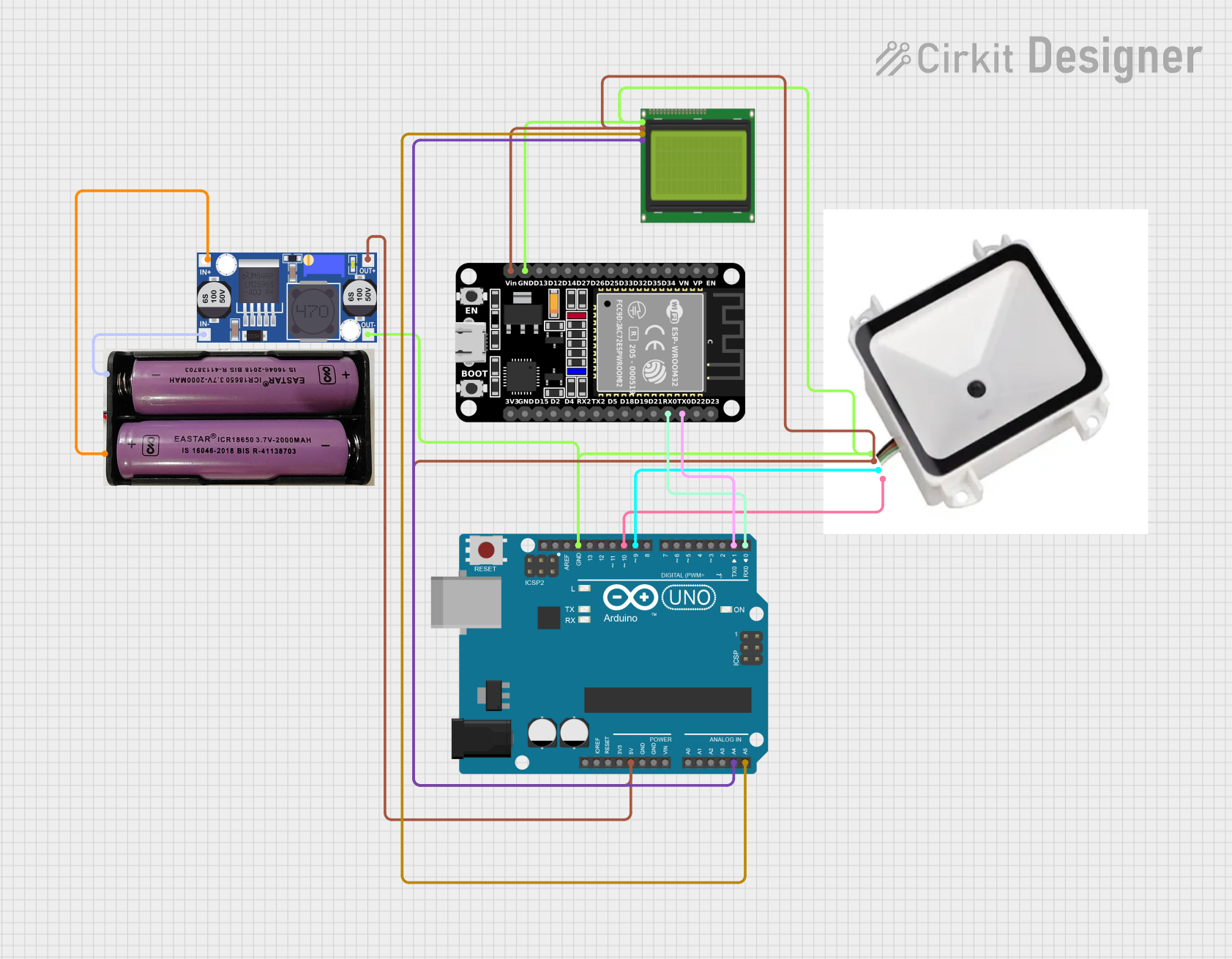
Circuit Documentation
Summary
This document provides a detailed overview of a circuit that integrates an ESP32 microcontroller, an Arduino UNO, a QR code reader, an LCD display, a buck converter, and a 7.4V power source. The circuit is designed to read QR codes and display the information on an LCD screen. The ESP32 and Arduino UNO communicate with each other and other peripherals to achieve this functionality.
Component List
ESP32 (30 pin)
- Description: A powerful microcontroller with built-in Wi-Fi and Bluetooth capabilities.
- Pins: EN, VP, VN, D34, D35, D32, D33, D25, D26, D27, D14, D12, D13, GND, Vin, D23, D22, TX0, RX0, D21, D19, D18, D5, TX2, RX2, D4, D2, D15, 3V3
QR Code Reader
- Description: A device used to scan and decode QR codes.
- Pins: GND, 5V, RX, TX
Arduino UNO
- Description: A popular microcontroller board based on the ATmega328P.
- Pins: UNUSED, IOREF, Reset, 3.3V, 5V, GND, Vin, A0, A1, A2, A3, A4, A5, SCL, SDA, AREF, D13, D12, D11, D10, D9, D8, D7, D6, D5, D4, D3, D2, D1, D0
LCD 20x4 I2C
- Description: A 20x4 character LCD display with I2C interface.
- Pins: GND, 5V, SCA, SCL
7.4V Battery
- Description: A power source providing 7.4V.
- Pins: +, -
Buck Converter
- Description: A DC-DC converter used to step down voltage.
- Pins: IN+, IN-, OUT+, OUT-
Wiring Details
ESP32 (30 pin)
- GND connected to GND of QR Code Reader, Buck Converter, Arduino UNO, and LCD 20x4 I2C.
- Vin connected to 5V of QR Code Reader, OUT+ of Buck Converter, 5V of Arduino UNO, and 5V of LCD 20x4 I2C.
- TX0 connected to D1 of Arduino UNO.
- RX0 connected to D0 of Arduino UNO.
QR Code Reader
- GND connected to GND of ESP32, Buck Converter, Arduino UNO, and LCD 20x4 I2C.
- 5V connected to Vin of ESP32, OUT+ of Buck Converter, 5V of Arduino UNO, and 5V of LCD 20x4 I2C.
- RX connected to D9 of Arduino UNO.
- TX connected to D10 of Arduino UNO.
Arduino UNO
- GND connected to GND of ESP32, QR Code Reader, Buck Converter, and LCD 20x4 I2C.
- 5V connected to Vin of ESP32, 5V of QR Code Reader, OUT+ of Buck Converter, and 5V of LCD 20x4 I2C.
- D1 connected to TX0 of ESP32.
- D0 connected to RX0 of ESP32.
- D9 connected to RX of QR Code Reader.
- D10 connected to TX of QR Code Reader.
- A4 connected to SCA of LCD 20x4 I2C.
- A5 connected to SCL of LCD 20x4 I2C.
LCD 20x4 I2C
- GND connected to GND of ESP32, QR Code Reader, Buck Converter, and Arduino UNO.
- 5V connected to Vin of ESP32, 5V of QR Code Reader, OUT+ of Buck Converter, and 5V of Arduino UNO.
- SCA connected to A4 of Arduino UNO.
- SCL connected to A5 of Arduino UNO.
7.4V Battery
- + connected to IN+ of Buck Converter.
- - connected to IN- of Buck Converter.
Buck Converter
- IN+ connected to + of 7.4V Battery.
- IN- connected to - of 7.4V Battery.
- OUT+ connected to Vin of ESP32, 5V of QR Code Reader, 5V of Arduino UNO, and 5V of LCD 20x4 I2C.
- OUT- connected to GND of ESP32, QR Code Reader, Arduino UNO, and LCD 20x4 I2C.
Documented Code
Arduino UNO Code
void setup() {
  // put your setup code here, to run once:

}

void loop() {
  // put your main code here, to run repeatedly:

}
This code is a basic template for the Arduino UNO. The setup function is used to initialize any settings or configurations, and the loop function contains the main code that runs repeatedly. Further implementation is required to handle QR code reading and displaying the information on the LCD.