
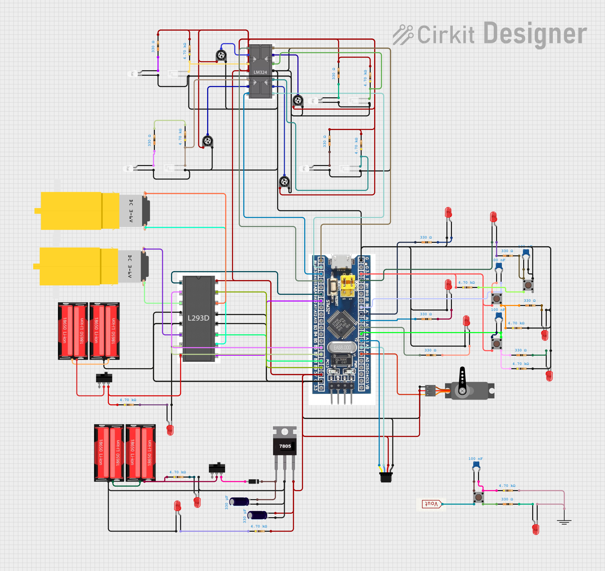
Circuit Documentation
Summary
This circuit appears to be a microcontroller-based system designed around the STM32F103C8T6 microcontroller. The circuit includes a variety of components such as LEDs, resistors, capacitors, a servo motor, pushbuttons, a motor driver (l293d), voltage regulators, and sensors like phototransistors. The microcontroller interfaces with these components to perform various functions, which could include sensing, actuation, and user interaction through buttons and LEDs. The code provided for the microcontroller is minimal, suggesting that the specific functionalities are yet to be implemented.
Component List
Microcontroller
- STM32F103C8T6: A 32-bit microcontroller with various I/O pins for interfacing with external components.
Passive Components
- Resistors: Various resistors with resistance values ranging from 330 Ohms to 4700 Ohms, used for current limiting and voltage division.
- Ceramic Capacitors: Capacitors with a capacitance of 100 nF, typically used for noise filtering and decoupling applications.
- Electrolytic Capacitors: Capacitors with a capacitance of 330 µF, likely used for power supply smoothing.
Active Components
- LEDs: Red and white LEDs used as visual indicators.
- Phototransistors: Sensors that detect light levels.
- lm324: A quad operational amplifier used for signal conditioning or other analog functions.
- l293d: A motor driver IC capable of driving motors or other inductive loads.
Electromechanical Components
- Servo: An electromechanical device that can be precisely controlled for position.
- Pushbuttons: User interface components for input.
- Toggle Switch: A switch that can maintain its state, used for turning circuits on or off.
- Motors: Hobbyist yellow geared motors for mechanical actuation.
Power Components
- 7805: A voltage regulator that outputs a stable 5V from a higher voltage input.
- Diode: Used for protecting the circuit from reverse voltage conditions.
- 18650 Li-Ion Batteries: Rechargeable batteries providing the power source for the circuit.
Connectors and Cables
- Qwiic Cable - Breadboard Jumper (4-pin): A cable used for making quick connections between components, typically I2C communication lines.
Miscellaneous
- Trimmer Potentiometer: An adjustable resistor used for setting voltage levels or calibrating the circuit.
- GND: A common ground reference point for the circuit.
- Vout: A generic voltage output component.
Wiring Details
STM32F103C8T6 Microcontroller
- GND: Connected to the ground plane.
- 3.3V: Powers the microcontroller and other 3.3V components.
- Reset: Connected to a reset circuit or a pushbutton for resetting the microcontroller.
- Digital/Analog Pins (A0-A10, B0-B15): Various I/O pins connected to LEDs, resistors, capacitors, phototransistors, and the motor driver for control and sensing purposes.
LEDs
- Anode: Connected to the microcontroller through a current-limiting resistor.
- Cathode: Connected to the ground plane.
Resistors
- Used for current limiting for LEDs and as pull-up/pull-down resistors for buttons and other inputs.
Capacitors
- Ceramic capacitors are typically placed close to power supply pins for decoupling.
- Electrolytic capacitors are used for power supply smoothing.
Servo
- PWM: Controlled by a PWM signal from the microcontroller.
- VCC: Powered by a 5V supply from the voltage regulator.
- GND: Connected to the ground plane.
Pushbuttons
- Connected to the microcontroller for user input, with pull-up or pull-down resistors as needed.
Motor Driver (l293d)
- Inputs: Controlled by the microcontroller to drive the motors.
- Outputs: Connected to the motors.
- Enable Pins: Controlled by the microcontroller to enable or disable the motor outputs.
- Vcc1: Logic supply voltage.
- Vcc2: Motor supply voltage.
- GND: Connected to the ground plane.
Phototransistors
- Connected to the microcontroller and the operational amplifier for light sensing.
lm324 Operational Amplifier
- Inputs: Connected to phototransistors and trimmer potentiometers.
- Outputs: Connected to the microcontroller for analog signal processing.
Power Components
- 7805 Voltage Regulator: Provides a stable 5V output from a higher voltage input.
- Diode: Placed in series with the power supply to prevent reverse current flow.
Batteries
- 18650 Li-Ion: Provides power to the circuit, with connections to the voltage regulator and motor driver.
Documented Code
Microcontroller Code (STM32F103C8T6)
void setup() {
  // put your setup code here, to run once:

}

void loop() {
  // put your main code here, to run repeatedly:

}
The provided code is a template with empty setup() and loop() functions, which are the starting points for writing the application code for the STM32F103C8T6 microcontroller. The setup() function is called once at the start, and the loop() function is called repeatedly, allowing the microcontroller to perform tasks continuously.