ESP32-Controlled Robotic Vehicle with Servo Steering and DC Motor Drive
Circuit Documentation
Summary
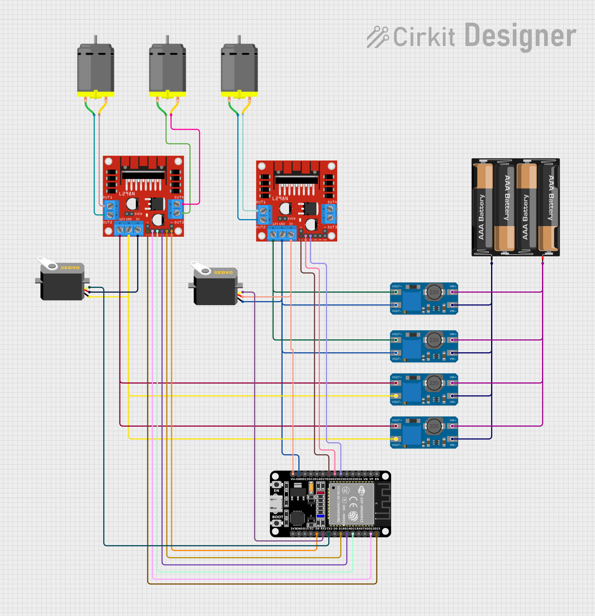
This circuit is designed to control multiple DC motors and servos using an ESP32 microcontroller and L298N motor drivers. The ESP32 is responsible for generating control signals that are sent to the L298N drivers, which in turn drive the motors. The servos are directly controlled by the ESP32 through PWM signals. The circuit is powered by a 4 x AAA battery mount, and the voltage is boosted as needed by MT3608 step-up converters.
Component List
ESP32 (30 pin)
- Description: A microcontroller with WiFi and Bluetooth capabilities, featuring a wide range of GPIO pins.
- Pins: EN, VP, VN, D34, D35, D32, D33, D25, D26, D27, D14, D12, D13, GND, Vin, D23, D22, TX0, RX0, D21, D19, D18, D5, TX2, RX2, D4, D2, D15, 3V3
Servo
- Description: An actuator that can be precisely controlled to move to a specific position using a PWM signal.
- Pins: gnd, vcc, pulse
L298N DC Motor Driver
- Description: A dual H-bridge motor driver capable of driving two DC motors.
- Pins: OUT1, OUT2, 12V, GND, 5V, OUT3, OUT4, 5V-ENA-JMP-I, 5V-ENA-JMP-O, +5V-J1, +5V-J2, ENA, IN1, IN2, IN3, IN4, ENB
MT3608
- Description: A DC-DC step-up converter that boosts the input voltage to a higher output voltage.
- Pins: VOUT+, VIN+, VOUT-, VIN-
4 x AAA Battery Mount
- Description: A battery holder for four AAA batteries, providing a power source for the circuit.
- Pins: -, +
DC Motor
- Description: An electric motor that runs on direct current (DC) electricity.
- Pins: pin 1, pin 2
Wiring Details
ESP32 (30 pin)
- D33 connected to L298N DC motor driver IN2
- D25 connected to L298N DC motor driver IN1
- D26 connected to L298N DC motor driver ENA
- GND connected to common ground net
- Vin connected to L298N DC motor driver 5V and Servo vcc
- D23 connected to L298N DC motor driver ENA
- D22 connected to L298N DC motor driver IN1
- D21 connected to L298N DC motor driver IN2
- D19 connected to L298N DC motor driver IN3
- D18 connected to L298N DC motor driver IN4
- TX2 connected to Servo pulse
- RX2 connected to Servo pulse
- D4 connected to L298N DC motor driver ENB
Servo
- gnd connected to common ground net
- vcc connected to ESP32 Vin
- pulse connected to ESP32 TX2 or RX2
L298N DC Motor Driver
- IN1, IN2, IN3, IN4 connected to ESP32 D25, D33, D19, D18 respectively
- ENA, ENB connected to ESP32 D26, D23, D4
- GND connected to common ground net
- 5V connected to ESP32 Vin
- OUT1, OUT2 connected to DC Motor pin 1, pin 2
- 12V connected to MT3608 VOUT+
MT3608
- VOUT+ connected to L298N DC motor driver 12V
- VIN+ connected to 4 x AAA Battery Mount +
- VOUT- connected to common ground net
- VIN- connected to 4 x AAA Battery Mount -
4 x AAA Battery Mount
- connected to MT3608 VIN+
- connected to common ground net
DC Motor
- pin 1, pin 2 connected to L298N DC motor driver OUT1, OUT2
Documented Code
No code was provided for the microcontrollers in the circuit. The documentation of the code would typically include a description of the functionality implemented, the setup and loop functions for an Arduino-based microcontroller like the ESP32, and any functions or libraries used to control the peripherals such as the DC motors and servos.