
Arduino-Based RC Controlled DC Motor System with Battery Power
View and Edit Project In Cirkit Designer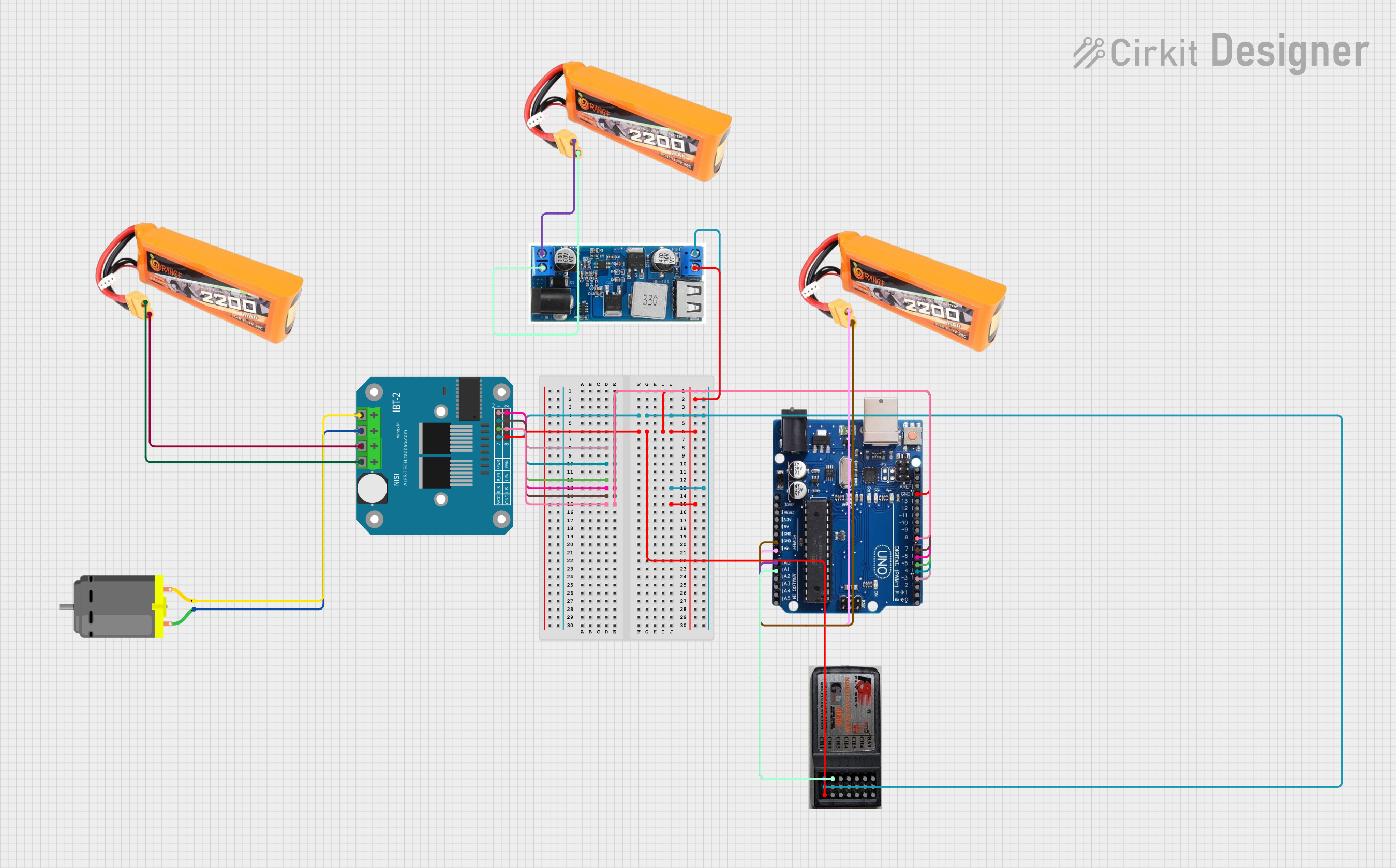
Circuit Documentation
Summary
This document provides a detailed overview of a circuit designed to control a DC motor using an Arduino Uno R3, a BTS7960 Motor Driver, and an RC Receiver. The circuit is powered by multiple LiPo batteries and includes a buck converter to step down the voltage. The Arduino Uno R3 is programmed to control the motor driver based on signals received from the RC Receiver.
Component List
DC Motor
- Description: A motor that converts electrical energy into mechanical energy.
- Pins: pin 1, pin 2
RC Receiver 6 channels
- Description: A receiver that can receive signals from an RC transmitter.
- Pins: CH1, VCC, GND, CH2, CH3, CH4, CH5, CH6, Bind
LiPo Battery 2200mAH 30C
- Description: A rechargeable lithium polymer battery.
- Pins: VCC, GND
BTS7960 Motor Driver
- Description: A high-power motor driver module.
- Pins: Pin 1, Pin 2, Pin 3, Pin 4, Pin 5, Pin 6, Pin 7, Pin 8, Pin 9, Pin 10, Pin 11, Pin 12
Arduino Uno R3
- Description: A microcontroller board based on the ATmega328P.
- Pins: USB Port, Power Jack, Not Connected, IOREF, RESET, 3.3V, 5V, GND, VIN, A0, A1, A2, A3, A4/SDA, A5/SCL, SCL, SDA, AREF, 13, 12, 11, 10, 9, 8, 7, 6, 5, 4, 3, 2, 1, 0
24/12V Buck Converter
- Description: A DC-DC converter that steps down voltage.
- Pins: VIN+, VIN-, 5V, GND
Wiring Details
DC Motor
- pin 1 is connected to Pin 10 of the BTS7960 Motor Driver.
- pin 2 is connected to Pin 9 of the BTS7960 Motor Driver.
RC Receiver 6 channels
- VCC is connected to Pin 5 of the BTS7960 Motor Driver and 5V of the 24/12V Buck Converter.
- GND is connected to Pin 1 of the BTS7960 Motor Driver, GND of the Arduino Uno R3, and GND of the 24/12V Buck Converter.
- CH1 is connected to A0 of the Arduino Uno R3.
- CH2 is connected to A1 of the Arduino Uno R3.
LiPo Battery 2200mAH 30C
- VCC of one battery is connected to VIN of the Arduino Uno R3.
- GND of one battery is connected to GND of the Arduino Uno R3.
- VCC of another battery is connected to Pin 12 of the BTS7960 Motor Driver.
- GND of another battery is connected to Pin 11 of the BTS7960 Motor Driver.
- VCC of the third battery is connected to VIN+ of the 24/12V Buck Converter.
- GND of the third battery is connected to VIN- of the 24/12V Buck Converter.
BTS7960 Motor Driver
- Pin 1 is connected to GND of the Arduino Uno R3 and GND of the RC Receiver 6 channels.
- Pin 2 is connected to 8 of the Arduino Uno R3.
- Pin 3 is connected to 7 of the Arduino Uno R3.
- Pin 4 is connected to 6 of the Arduino Uno R3.
- Pin 5 is connected to VCC of the RC Receiver 6 channels and 5V of the 24/12V Buck Converter.
- Pin 6 is connected to 5 of the Arduino Uno R3.
- Pin 7 is connected to 4 of the Arduino Uno R3.
- Pin 8 is connected to 3 of the Arduino Uno R3.
- Pin 9 is connected to pin 2 of the DC Motor.
- Pin 10 is connected to pin 1 of the DC Motor.
- Pin 11 is connected to GND of the LiPo Battery 2200mAH 30C.
- Pin 12 is connected to VCC of the LiPo Battery 2200mAH 30C.
Arduino Uno R3
- GND is connected to Pin 1 of the BTS7960 Motor Driver, GND of the RC Receiver 6 channels, and GND of the LiPo Battery 2200mAH 30C.
- VIN is connected to VCC of the LiPo Battery 2200mAH 30C.
- A0 is connected to CH1 of the RC Receiver 6 channels.
- A1 is connected to CH2 of the RC Receiver 6 channels.
- 3 is connected to Pin 8 of the BTS7960 Motor Driver.
- 4 is connected to Pin 7 of the BTS7960 Motor Driver.
- 5 is connected to Pin 6 of the BTS7960 Motor Driver.
- 6 is connected to Pin 4 of the BTS7960 Motor Driver.
- 7 is connected to Pin 3 of the BTS7960 Motor Driver.
- 8 is connected to Pin 2 of the BTS7960 Motor Driver.
24/12V Buck Converter
- VIN+ is connected to VCC of the LiPo Battery 2200mAH 30C.
- VIN- is connected to GND of the LiPo Battery 2200mAH 30C.
- 5V is connected to VCC of the RC Receiver 6 channels and Pin 5 of the BTS7960 Motor Driver.
- GND is connected to Pin 1 of the BTS7960 Motor Driver, GND of the Arduino Uno R3, and GND of the RC Receiver 6 channels.
Documented Code
Arduino Uno R3 Code
void setup() {
  // put your setup code here, to run once:

}

void loop() {
  // put your main code here, to run repeatedly:

}
This code is a basic template for the Arduino Uno R3. The setup() function is where you initialize your variables, pin modes, start using libraries, etc. The loop() function is where you write the code that you want to run repeatedly.