
Arduino-Controlled DC Motor with Speed Regulation and Safety Switches
View and Edit Project In Cirkit Designer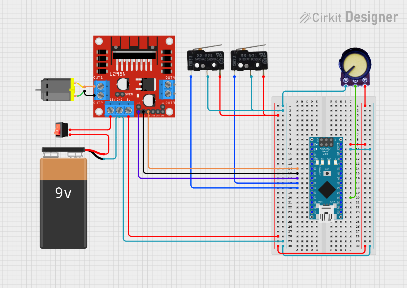
Circuit Documentation
Summary of the Circuit
This circuit appears to be designed to control a DC motor using an Arduino Nano as the central processing unit, interfaced with a L298N DC motor driver. The motor's operation can be influenced by the state of two micro switches and a potentiometer. A 9V battery provides power to the system, with a rocker switch included to control power flow. The Arduino Nano is responsible for processing the input signals and controlling the motor driver, which in turn drives the DC motor.
Component List
Micro Switch
- Description: A switch that opens and closes an electrical circuit.
- Pins: COM (Common), NO (Normally Open), NC (Normally Closed)
Arduino Nano
- Description: A small, complete, and breadboard-friendly board based on the ATmega328 (Arduino Nano 3.x).
- Pins: D1/TX, D0/RX, RESET, GND, D2, D3, D4, D5, D6, D7, D8, D9, D10, D11/MOSI, D12/MISO, VIN, 5V, A7, A6, A5, A4, A3, A2, A1, A0, AREF, 3V3, D13/SCK
9V Battery
- Description: A standard 9V battery used to provide power to the circuit.
- Pins: -, +
L298N DC Motor Driver
- Description: A dual H-bridge motor driver that can drive two DC motors or one stepper motor.
- Pins: OUT1, OUT2, 12V, GND, 5V, OUT3, OUT4, 5V-ENA-JMP-I, 5V-ENA-JMP-O, +5V-J1, +5V-J2, ENA, IN1, IN2, IN3, IN4, ENB
Rocker Switch
- Description: A switch that rocks back and forth to open or close the circuit.
- Pins: Output, Input
DC Motor
- Description: An electric motor that runs on direct current (DC) electricity.
- Pins: Pin 1, Pin 2
Potentiometer
- Description: A three-terminal resistor with a sliding or rotating contact that forms an adjustable voltage divider.
- Pins: GND, Output, VCC
Wiring Details
Micro Switch
- COM - Connected to Arduino Nano D6 or D7 (depending on the instance of the micro switch)
- NO - Connected to GND
- NC - Connected to VIN (5V)
Arduino Nano
- VIN - Connected to Potentiometer VCC, Micro Switch NC, and L298N DC motor driver 5V
- GND - Connected to Potentiometer GND, Micro Switch NO, 9V Battery -, and L298N DC motor driver GND
- D3 - Connected to L298N DC motor driver IN2
- D4 - Connected to L298N DC motor driver IN1
- D5 - Connected to L298N DC motor driver ENA
- D6 - Connected to Micro Switch COM (first instance)
- D7 - Connected to Micro Switch COM (second instance)
- A0 - Connected to Potentiometer Output
9V Battery
- + - Connected to rocker switch input
- - - Connected to Arduino Nano GND
L298N DC Motor Driver
- 12V - Connected to rocker switch output
- GND - Connected to Arduino Nano GND
- 5V - Connected to Arduino Nano VIN
- OUT1 - Connected to DC Motor pin 2
- OUT2 - Connected to DC Motor pin 1
- IN1 - Connected to Arduino Nano D4
- IN2 - Connected to Arduino Nano D3
- ENA - Connected to Arduino Nano D5
Rocker Switch
- Input - Connected to 9V Battery +
- Output - Connected to L298N DC motor driver 12V
DC Motor
- Pin 1 - Connected to L298N DC motor driver OUT2
- Pin 2 - Connected to L298N DC motor driver OUT1
Potentiometer
- GND - Connected to Arduino Nano GND
- Output - Connected to Arduino Nano A0
- VCC - Connected to Arduino Nano VIN
Documented Code
void setup() {
  // put your setup code here, to run once:

}

void loop() {
  // put your main code here, to run repeatedly:

}
Filename: sketch.ino
Note: The provided code is a template and does not contain any functional code to control the circuit. The actual implementation would require additional code to read inputs from the micro switches and potentiometer, and to control the motor driver accordingly.