ESP32-Based Smart Power Monitoring System with Wi-Fi Connectivity
Circuit Documentation
Summary
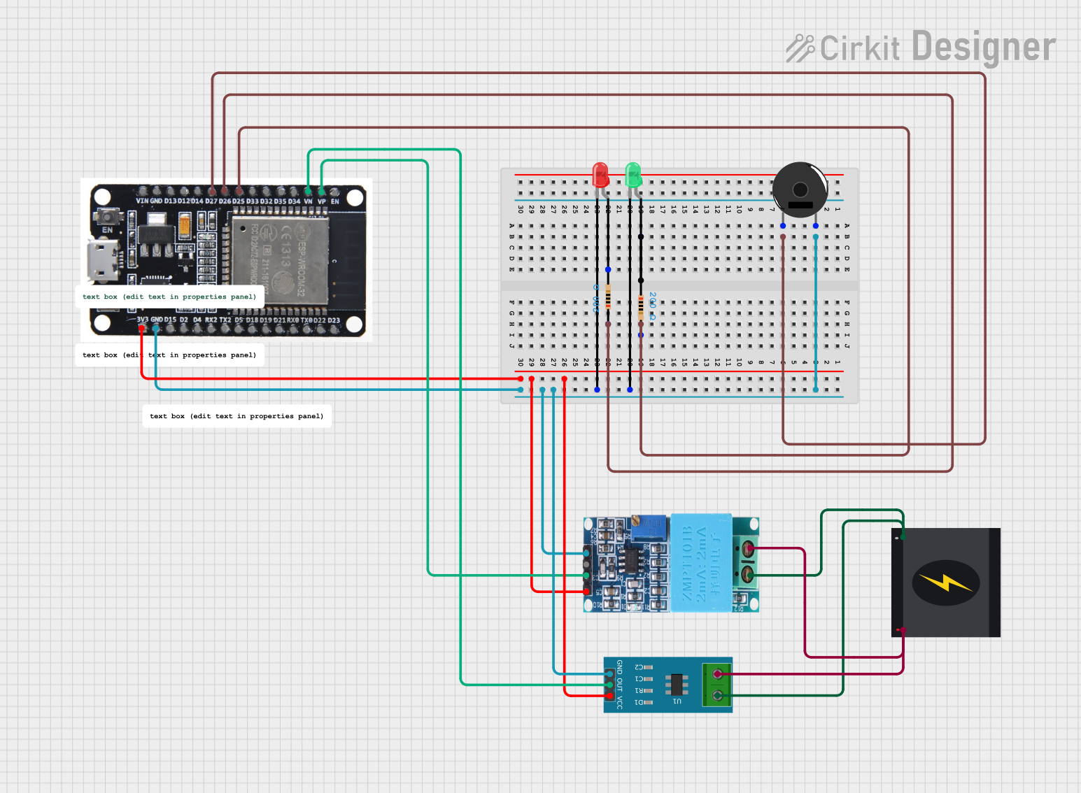
This document provides a detailed overview of a circuit that includes a 240V power source, various sensors, an ESP32 microcontroller, LEDs, a piezo buzzer, and resistors. The circuit is designed to monitor current and voltage, and it includes visual and auditory indicators.
Component List
240V Power Source
- Pins: Live, Neutral
- Description: Provides the main power supply for the circuit.
ZMPT101B
- Pins: OUT, GND, VCC, NEUTRO, FASE
- Description: Voltage sensor module for measuring AC voltage.
ESP32
- Pins: EN, VP, VN, D34, D35, D32, D33, D25, D26, D27, D14, D12, D13, GND, VIN, 3V3, D15, D2, D4, RX2, TX2, D5, D18, D19, D21, RX0, TX0, D22, D23, BOOT
- Description: Microcontroller with Wi-Fi and Bluetooth capabilities.
LED: Two Pin (red)
- Pins: cathode, anode
- Description: Red LED for visual indication.
LED: Two Pin (green)
- Pins: cathode, anode
- Description: Green LED for visual indication.
Piezo Buzzer
- Pins: pin 1, pin 2
- Description: Buzzer for auditory indication.
Resistor (200 Ohms)
- Pins: pin1, pin2
- Description: Resistor to limit current.
Current Sensor 5A
- Pins: 1, 2, GND, OUT, VCC
- Description: Sensor for measuring current up to 5A.
Wiring Details
240V Power Source
Live is connected to:
- ZMPT101B (FASE)
- Current Sensor 5A (2)
Neutral is connected to:
- ZMPT101B (NEUTRO)
- Current Sensor 5A (1)
ZMPT101B
OUT is connected to:
- ESP32 (VP)
GND is connected to:
- Piezo Buzzer (pin 2)
- LED: Two Pin (red) (cathode)
- LED: Two Pin (green) (cathode)
- Current Sensor 5A (GND)
- ESP32 (GND)
VCC is connected to:
- Current Sensor 5A (VCC)
- ESP32 (3V3)
NEUTRO is connected to:
- Current Sensor 5A (1)
- 240V Power Source (Neutral)
FASE is connected to:
- Current Sensor 5A (2)
- 240V Power Source (Live)
ESP32
GND is connected to:
- Piezo Buzzer (pin 2)
- LED: Two Pin (red) (cathode)
- LED: Two Pin (green) (cathode)
- Current Sensor 5A (GND)
- ZMPT101B (GND)
D27 is connected to:
- Piezo Buzzer (pin 1)
D25 is connected to:
- Resistor (pin2)
D26 is connected to:
- Resistor (pin1)
3V3 is connected to:
- Current Sensor 5A (VCC)
- ZMPT101B (VCC)
VP is connected to:
- ZMPT101B (OUT)
VN is connected to:
- Current Sensor 5A (OUT)
LED: Two Pin (red)
cathode is connected to:
- Piezo Buzzer (pin 2)
- LED: Two Pin (green) (cathode)
- Current Sensor 5A (GND)
- ZMPT101B (GND)
- ESP32 (GND)
anode is connected to:
- Resistor (pin2)
LED: Two Pin (green)
cathode is connected to:
- Piezo Buzzer (pin 2)
- LED: Two Pin (red) (cathode)
- Current Sensor 5A (GND)
- ZMPT101B (GND)
- ESP32 (GND)
anode is connected to:
- Resistor (pin1)
Piezo Buzzer
pin 1 is connected to:
- ESP32 (D27)
pin 2 is connected to:
- LED: Two Pin (red) (cathode)
- LED: Two Pin (green) (cathode)
- Current Sensor 5A (GND)
- ZMPT101B (GND)
- ESP32 (GND)
Resistor (200 Ohms)
pin1 is connected to:
- ESP32 (D26)
- LED: Two Pin (green) (anode)
pin2 is connected to:
- ESP32 (D25)
- LED: Two Pin (red) (anode)
Current Sensor 5A
1 is connected to:
- ZMPT101B (NEUTRO)
- 240V Power Source (Neutral)
2 is connected to:
- ZMPT101B (FASE)
- 240V Power Source (Live)
GND is connected to:
- Piezo Buzzer (pin 2)
- LED: Two Pin (red) (cathode)
- LED: Two Pin (green) (cathode)
- ZMPT101B (GND)
- ESP32 (GND)
OUT is connected to:
- ESP32 (VN)
VCC is connected to:
- ZMPT101B (VCC)
- ESP32 (3V3)
Code Documentation
ESP32 Code
void setup() {
  // put your setup code here, to run once:

}

void loop() {
  // put your main code here, to run repeatedly:

}
This code is a basic template for the ESP32 microcontroller. The setup function is called once when the microcontroller starts, and the loop function runs continuously. You can add your specific logic and functionality within these functions.