Cirkit Designer
Your all-in-one circuit design IDE
Home /
Project Documentation
Arduino UNO Based Light Intensity Monitor with I2C LCD Display
Circuit Documentation
Summary
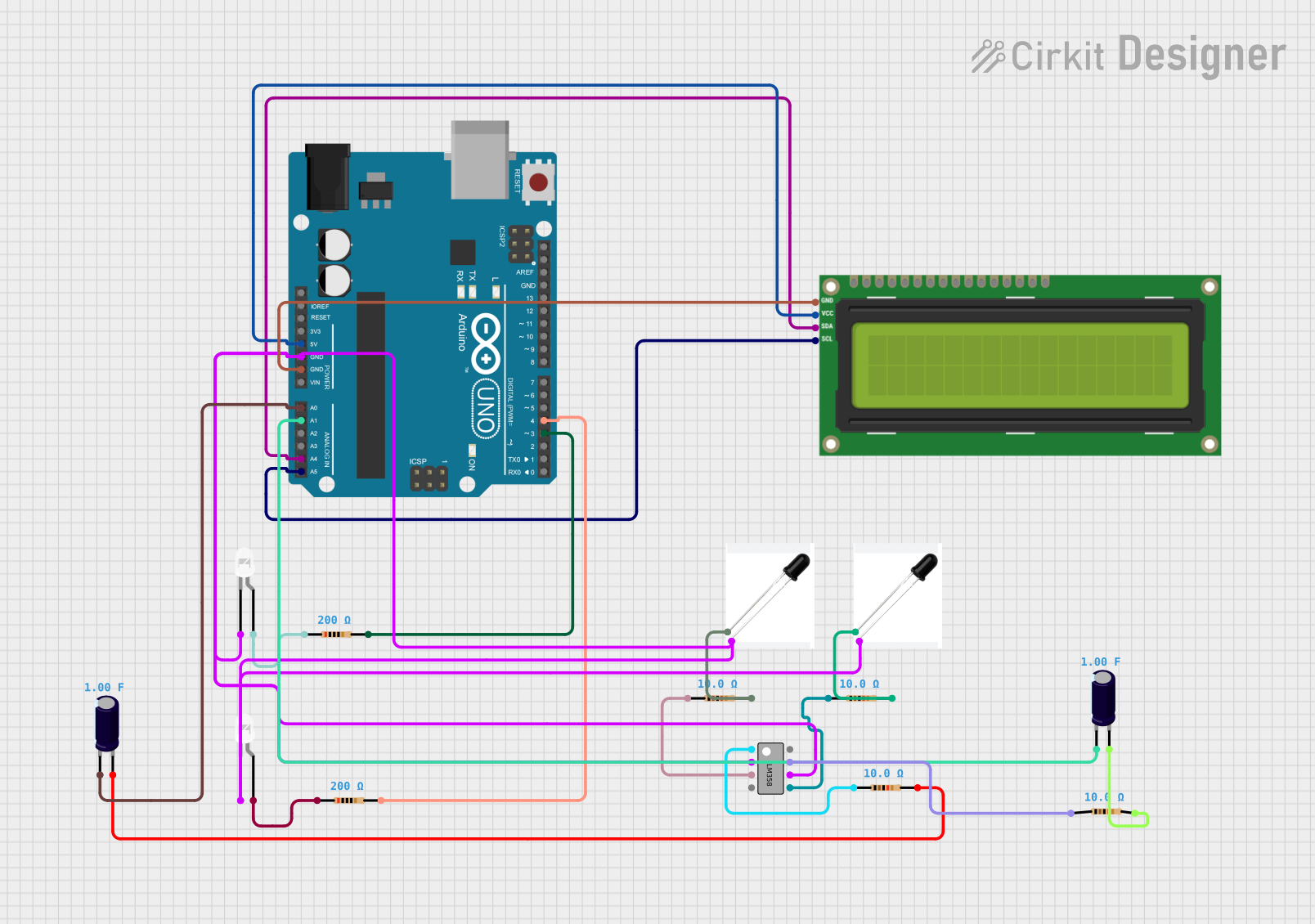
This circuit incorporates an Arduino UNO as the central microcontroller, interfaced with an I2C LCD 16x2 Screen for display purposes. The circuit also includes photodiodes for light detection, LEDs for indication, resistors for current limiting and voltage division, an LM358 operational amplifier for signal amplification, and electrolytic capacitors for filtering or timing purposes.
Component List
Arduino UNO
- Microcontroller board based on the ATmega328P
- Provides digital and analog I/O pins
- Powers the I2C LCD screen and provides communication via I2C
I2C LCD 16x2 Screen
- A liquid crystal display capable of displaying 16 characters per line across 2 lines
- Uses I2C communication protocol for interfacing with the Arduino UNO
Photodiodes
- Light-sensitive components that generate a current proportional to the light intensity
- Used for detecting light levels in the circuit
LEDs (White)
- Light Emitting Diodes used as visual indicators
- Requires current-limiting resistors to prevent damage
Resistors
- Passive components used for current limiting and voltage division
- Values range from 10 Ohms to 200 Ohms in this circuit
LM358
- A dual operational amplifier used for signal amplification and conditioning
Electrolytic Capacitors
- Polarized capacitors with a capacitance of 1 Farad
- Used for filtering or timing applications within the circuit
Wiring Details
Arduino UNO
5Vpin connected to theVCC (5V)pin of the I2C LCD ScreenGNDpin connected to theGNDpin of the I2C LCD Screen, cathodes of LEDs, and cathodes of PhotodiodesA0andA1pins connected to the-pins of Electrolytic CapacitorsA4(SDA) andA5(SCL) pins connected to the correspondingSDAandSCLpins of the I2C LCD ScreenD3andD4pins connected to thepin2of respective 200 Ohm Resistors
I2C LCD 16x2 Screen
VCC (5V)andGNDpins connected to the corresponding power supply pins on the Arduino UNOSDAandSCLpins connected to the I2C data and clock lines on the Arduino UNO
Photodiodes
Anodepins connected to the input pins of the LM358Cathodepins connected to the ground through 10 Ohm Resistors
LEDs (White)
Anodepins connected to thepin1of respective 200 Ohm ResistorsCathodepins connected to the ground
Resistors
- 200 Ohm Resistors connected between the
D3andD4pins of the Arduino UNO and the anodes of the LEDs - 10 Ohm Resistors connected between the cathodes of the Photodiodes and the ground
LM358
INPUT-andINPUT 2-pins connected to the cathodes of LEDs and PhotodiodesINPUT+andINPUT 2+pins connected to the anodes of Photodiodes through 10 Ohm ResistorsOUTPUT 1andOUTPUT 2pins connected to thepin1of 10 Ohm Resistors
Electrolytic Capacitors
-pins connected to theA0andA1pins of the Arduino UNO+pins connected to thepin2of 10 Ohm Resistors
Documented Code
Arduino UNO Code (sketch.ino)
void setup() {
  // put your setup code here, to run once:

}

void loop() {
  // put your main code here, to run repeatedly:

}
Additional Notes
- The provided code for the Arduino UNO is a template with empty
setup()andloop()functions. Actual implementation code is required for the circuit to perform specific tasks. - The
documentation.txtfile is mentioned but contains no code or content as per the provided input.