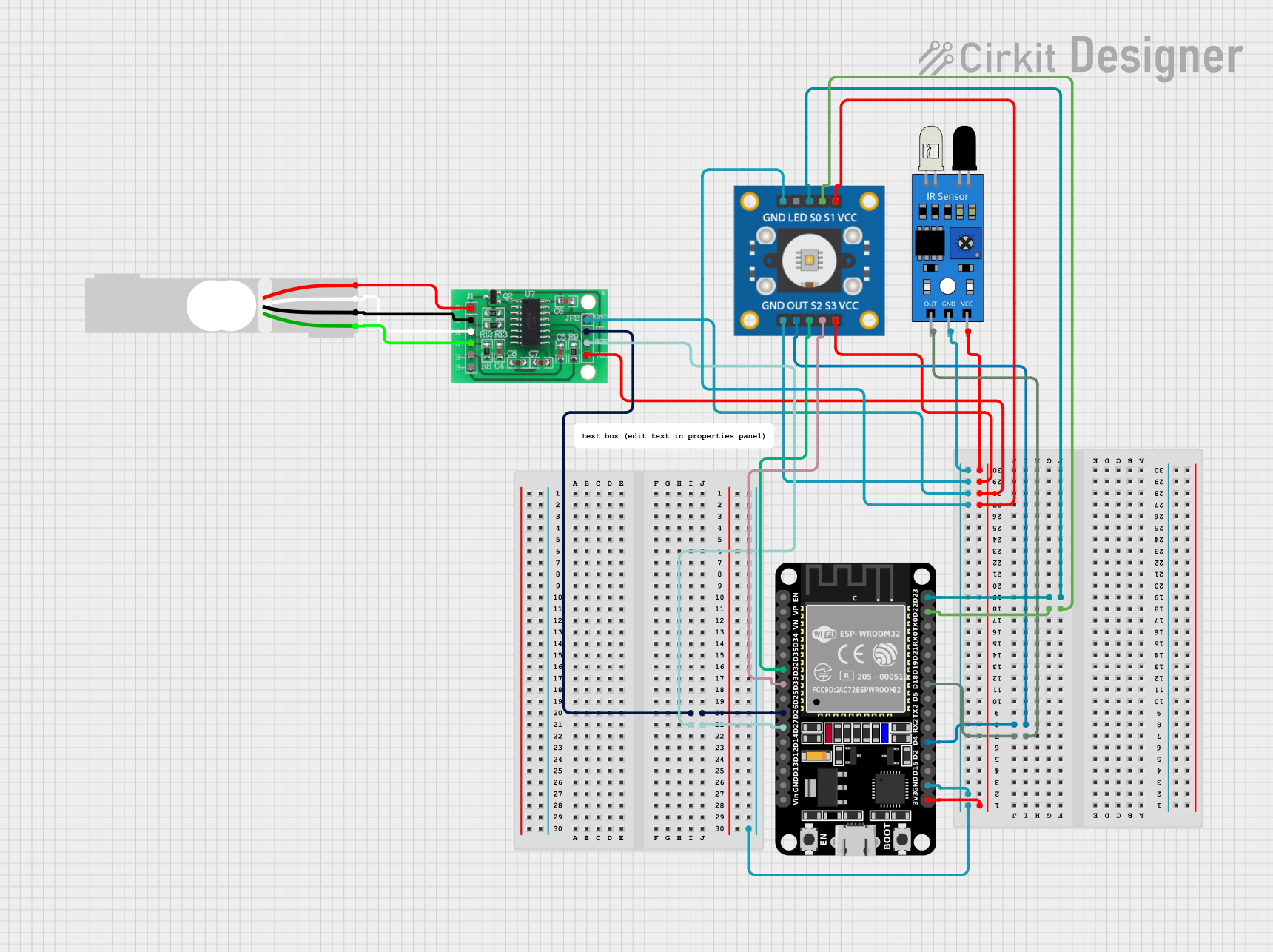
ESP32-Based Color and Weight Sensing System with IR Detection

Circuit Documentation
Summary
The circuit in question is designed to interface various sensors and modules with an ESP32 microcontroller. The components include a TCS3200 color sensor, an IR sensor, an HX711 bridge sensor interface, and a load cell. The ESP32 serves as the central processing unit, handling inputs from the sensors and potentially providing outputs based on the sensor data. The TCS3200 is used for detecting color, the IR sensor for detecting proximity or motion, and the load cell, in conjunction with the HX711, for measuring weight or force.
Component List
TCS3200 Color Sensor
- Description: A color sensor that can detect a wide spectrum of colors.
- Pins: GND, OUT, S2, S3, VCC, LED, S0, S1
IR Sensor
- Description: An infrared sensor typically used for proximity or motion detection.
- Pins: out, gnd, vcc
ESP32 (30 pin)
- Description: A powerful microcontroller with Wi-Fi and Bluetooth capabilities.
- Pins: EN, VP, VN, D34, D35, D32, D33, D25, D26, D27, D14, D12, D13, GND, Vin, D23, D22, TX0, RX0, D21, D19, D18, D5, TX2, RX2, D4, D2, D15, 3V3
HX711 - Bridge Sensor Interface
- Description: An ADC converter designed for weighing scales and industrial control applications to interface directly with a bridge sensor.
- Pins: E+, E-, A-, A+, B-, B+, GND - GROUND, DATA (OUT), SCK - CLOCK (IN), 3.3/3.5V Supply
Load Cell - Red/white/black/green
- Description: A transducer that converts force into an electrical signal.
- Pins: E+, A-, E-, A+
Wiring Details
TCS3200 Color Sensor
- OUT connected to ESP32 D4
- S1 connected to ESP32 D22
- S0 connected to ESP32 D23
- S2 connected to ESP32 D32
- S3 connected to ESP32 D33
- VCC connected to ESP32 3V3
- GND connected to ESP32 GND
IR Sensor
- out connected to ESP32 D18
- vcc connected to ESP32 3V3
- gnd connected to ESP32 GND
ESP32 (30 pin)
- 3V3 connected to TCS3200 VCC, HX711 3.3/3.5V Supply, IR Sensor vcc
- GND connected to TCS3200 GND, HX711 GND - GROUND, IR Sensor gnd
- D4 connected to TCS3200 OUT
- D18 connected to IR Sensor out
- D22 connected to TCS3200 S1
- D23 connected to TCS3200 S0
- D26 connected to HX711 DATA (OUT)
- D27 connected to HX711 SCK - CLOCK (IN)
- D32 connected to TCS3200 S2
- D33 connected to TCS3200 S3
HX711 - Bridge Sensor Interface
- DATA (OUT) connected to ESP32 D26
- SCK - CLOCK (IN) connected to ESP32 D27
- E+ connected to Load Cell E+
- A- connected to Load Cell A-
- E- connected to Load Cell E-
- A+ connected to Load Cell A+
- 3.3/3.5V Supply connected to ESP32 3V3
- GND - GROUND connected to ESP32 GND
Load Cell - Red/white/black/green
- E+ connected to HX711 E+
- A- connected to HX711 A-
- E- connected to HX711 E-
- A+ connected to HX711 A+
Documented Code
ESP32 Microcontroller Code (sketch.ino)
void setup() {
  // put your setup code here, to run once:

}

void loop() {
  // put your main code here, to run repeatedly:

}
This code is a template for the ESP32 microcontroller. The setup() function is called once when the microcontroller is powered on or reset. It is used to initialize variables, pin modes, start using libraries, etc. The loop() function is called repeatedly and contains the main logic of the code. It is where the microcontroller will read sensor data, perform calculations, and control other devices.
The actual implementation details will depend on the specific requirements of the application, such as how the sensors are to be read, what conditions are being monitored, and how the ESP32 should respond to different sensor inputs.