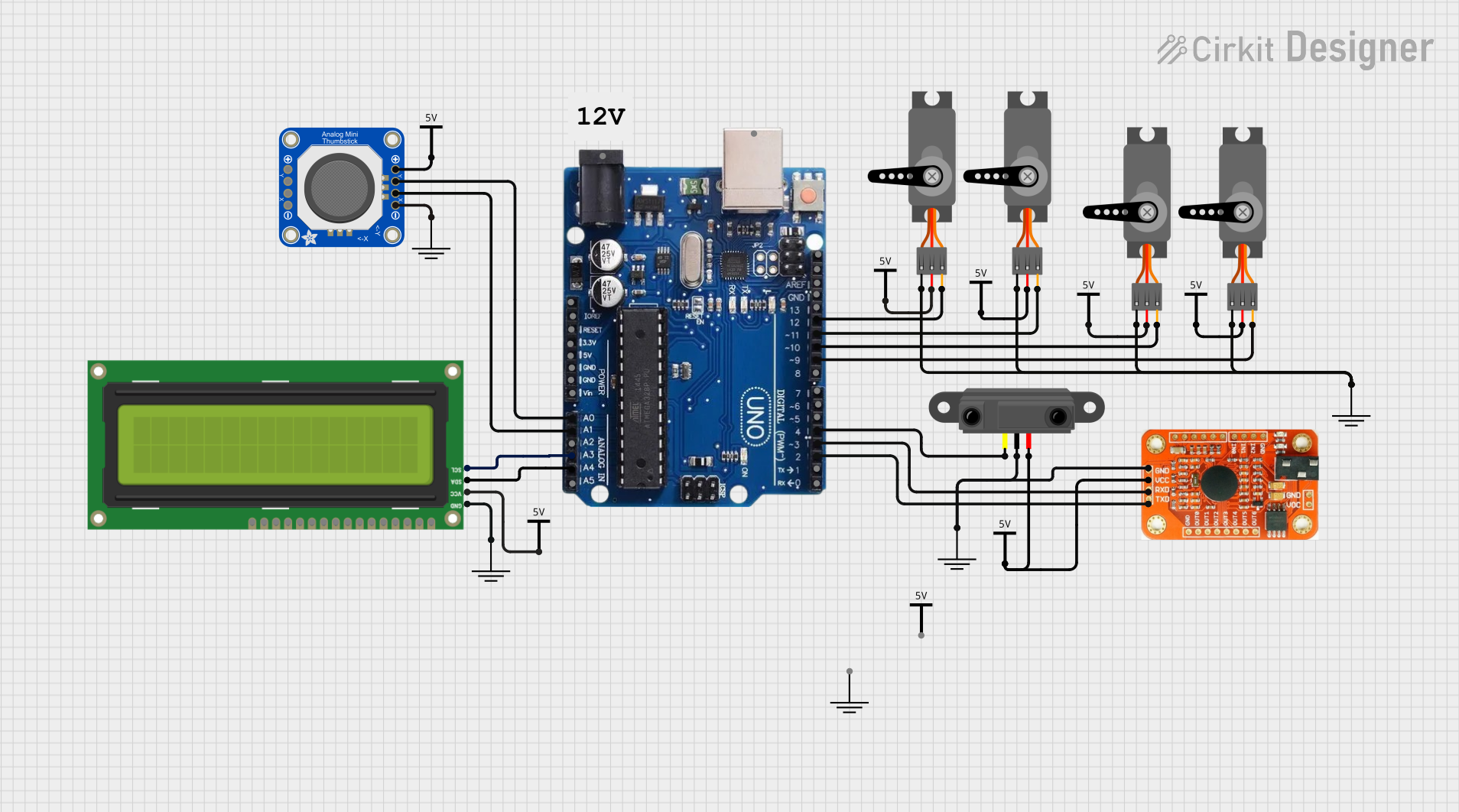
Arduino Uno R3-Based Voice-Controlled Robotic Interface with LCD Feedback

Circuit Documentation
Summary
This circuit integrates various components with an Arduino Uno R3 to create a system capable of receiving analog inputs from a thumbstick, processing infrared proximity sensor data, controlling multiple servos, and interfacing with a voice recognition module and an I2C LCD screen. The Arduino Uno R3 serves as the central processing unit, reading inputs and driving outputs based on programmed logic. The servos are controlled via PWM signals, and the thumbstick provides analog input for additional control or feedback. The voice recognition module allows for audio-based input, while the infrared sensor adds proximity sensing capabilities. The I2C LCD screen displays information or status messages.
Component List
- Arduino Uno R3: A microcontroller board based on the ATmega328P, equipped with digital I/O pins, analog inputs, and various power outputs.
- Voice Recognition Module: A module capable of recognizing voice commands and converting them to electronic signals.
- Adafruit Mini Analog Thumbstick: A joystick providing two analog outputs corresponding to the X and Y axes.
- Infrared Proximity Sensor: A sensor that detects the presence of objects within a certain range without physical contact.
- I2C LCD 16x2 Screen: A 16-character by 2-line display that communicates with the Arduino via the I2C protocol.
- Servo: An actuator capable of precise angular positioning, controlled by PWM signals.
- Vcc: A power supply component representing the positive voltage supply.
- GND: A ground reference component representing the common ground connection.
Wiring Details
Arduino Uno R3
- A0 connected to Adafruit Mini Analog Thumbstick YOUT
- A1 connected to Adafruit Mini Analog Thumbstick XOUT
- A3 connected to I2C LCD 16x2 Screen SCL
- A4/SDA connected to I2C LCD 16x2 Screen SDA
- Digital Pin 12 connected to Servo PWM
- Digital Pin 11 connected to Servo PWM
- Digital Pin 10 connected to Servo PWM
- Digital Pin 9 connected to Servo PWM
- Digital Pin 4 connected to Infrared Proximity Sensor Vout
- Digital Pin 3 connected to Voice Recognition Module RDX
- Digital Pin 2 connected to Voice Recognition Module RTX
Voice Recognition Module
- GND connected to common GND
- VCC connected to common Vcc
- RDX connected to Arduino Uno R3 Digital Pin 3
- RTX connected to Arduino Uno R3 Digital Pin 2
Adafruit Mini Analog Thumbstick
- VCC connected to common Vcc
- YOUT connected to Arduino Uno R3 A0
- XOUT connected to Arduino Uno R3 A1
- GND connected to common GND
Infrared Proximity Sensor
- Vout connected to Arduino Uno R3 Digital Pin 4
- GND connected to common GND
- Vcc connected to common Vcc
I2C LCD 16x2 Screen
- SCL connected to Arduino Uno R3 A3
- SDA connected to Arduino Uno R3 A4/SDA
- VCC (5V) connected to common Vcc
- GND connected to common GND
Servo
- GND connected to common GND
- VCC connected to common Vcc
- PWM connected to Arduino Uno R3 Digital Pins 9, 10, 11, or 12 (one servo per pin)
Documented Code
No code has been provided for the microcontrollers in the circuit. The documentation of the code would typically include descriptions of the functions, algorithms, and logic used to control the components based on the inputs received and the desired outputs. It would also include any libraries or external resources used within the code.