
Circuit Documentation
Summary of the Circuit
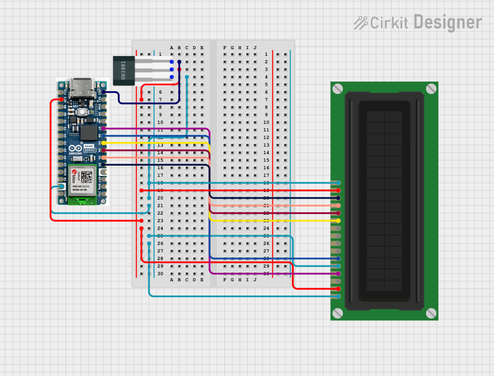
This circuit integrates a Hall Sensor, an Arduino Nano ESP32 microcontroller, and an LCD Display (16 pin). The Hall Sensor is used to detect magnetic fields and outputs a signal to the Arduino Nano ESP32. The Arduino processes this signal and displays relevant information on the LCD Display. The circuit is powered by a 3.3V supply from the Arduino, which is shared with the Hall Sensor and the LCD Display. Ground connections are also common across all components.
Component List
Hall Sensor
- Description: A sensor that detects magnetic fields and provides a digital output.
- Pins:
-: Ground+: Power supply (3.3V)S: Signal output to the Arduino Nano ESP32
Arduino Nano ESP32
- Description: A microcontroller board based on the ESP32. It is used to process inputs from the Hall Sensor and control the LCD Display.
- Pins:
- Digital I/O pins (
D2toD13) - Analog input pins (
A0toA7) - Power pins (
3.3V,GND,VIN) - Serial pins (
RX0,TX1) - Reset pin (
RST) - Additional function pins (
B0,B1,VBUS)
- Digital I/O pins (
LCD Display (16 pin)
- Description: A 16-pin Liquid Crystal Display used to show information processed by the Arduino Nano ESP32.
- Pins:
VSS: GroundVDD: Power supply (3.3V)VO: Contrast adjustmentRS: Register SelectR_W: Read/Write select (tied to Ground)E: EnableDB0toDB7: Data bus linesA: Anode for backlight (3.3V)K: Cathode for backlight (Ground)
Wiring Details
Hall Sensor
+connected to 3.3V power supply from the Arduino Nano ESP32-connected to Ground (GND) on the Arduino Nano ESP32Sconnected to digital pinD12on the Arduino Nano ESP32
Arduino Nano ESP32
3.3Vconnected to the Hall Sensor and theAandVDDpins of the LCD DisplayGNDconnected to the-pin of the Hall Sensor and theK,R_W, andVSSpins of the LCD DisplayD12connected to theSpin of the Hall SensorD7connected to theRSpin of the LCD DisplayD6connected to theEpin of the LCD DisplayD5toD2connected to theDB4toDB7pins of the LCD Display respectively
LCD Display (16 pin)
VDDconnected to 3.3V power supply from the Arduino Nano ESP32Aconnected to 3.3V power supply from the Arduino Nano ESP32K,R_W, andVSSconnected to Ground (GND) on the Arduino Nano ESP32RSconnected to digital pinD7on the Arduino Nano ESP32Econnected to digital pinD6on the Arduino Nano ESP32DB4toDB7connected to digital pinsD5toD2on the Arduino Nano ESP32 respectively
Documented Code
Since no code was provided, this section is left blank. When code is available, it should be documented here with explanations of how the microcontroller interfaces with the Hall Sensor and the LCD Display, including initialization, main loop, interrupt handling, and any other relevant functions or routines.