
Arduino-Based Smart Garden Automation System with Environmental Monitoring
View and Edit Project In Cirkit Designer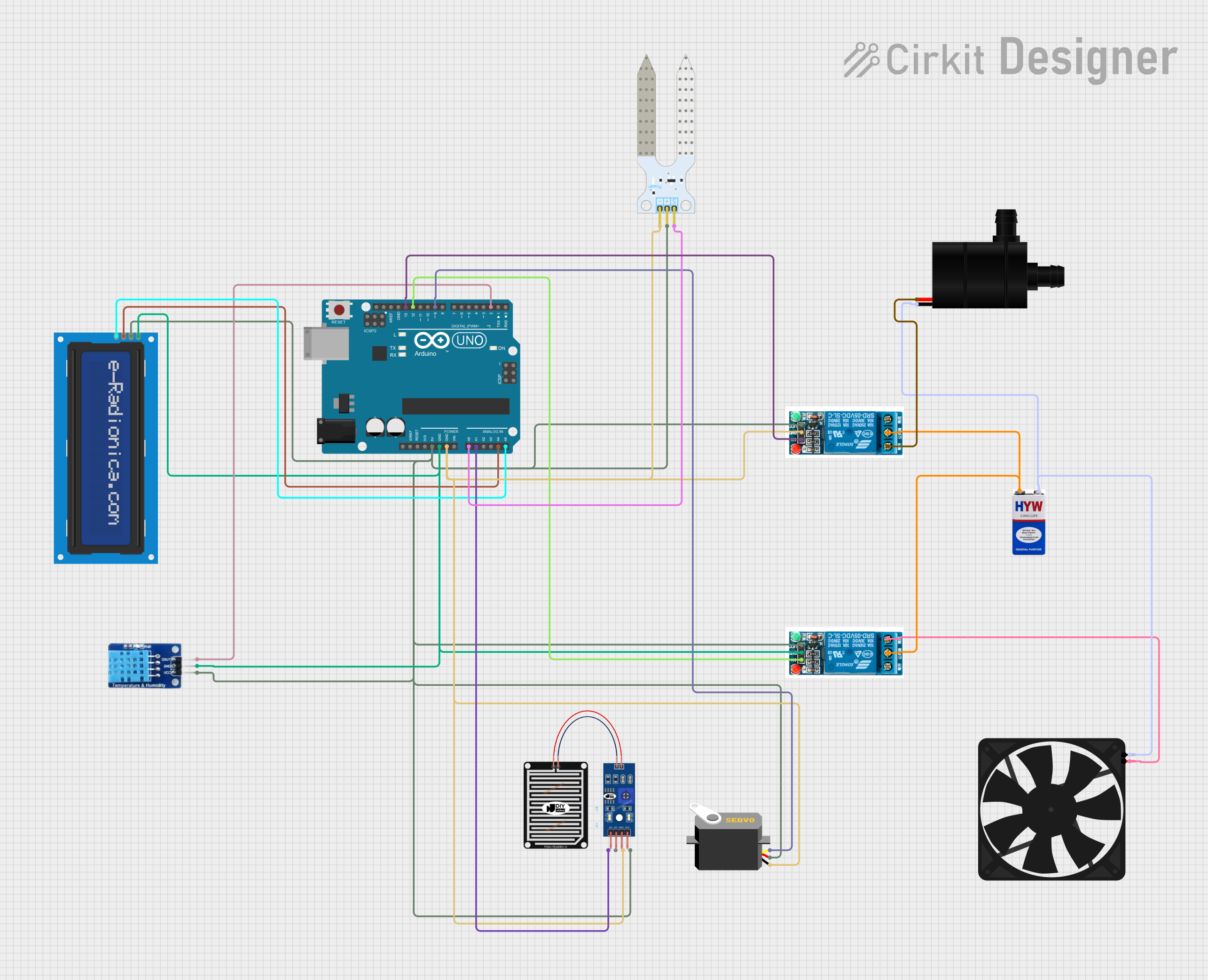
Circuit Documentation
Summary
This circuit is designed to interface various sensors and actuators with an Arduino UNO microcontroller. It includes environmental sensors, a display module, relays for controlling power to a fan and a water pump, and a servo motor. The circuit is powered by a 9V battery and regulated to 5V for the components that require it. The Arduino UNO reads sensor data and controls the actuators accordingly.
Component List
- Arduino UNO: A microcontroller board based on the ATmega328P. It has digital input/output pins, analog inputs, a USB connection for programming, and power management features.
- RAIN SENSOR: A sensor that detects rainwater. It has analog and digital outputs.
- 5V Relay (x2): Electromechanical switches that allow the Arduino to control higher power devices like the fan and water pump.
- LCD screen 16x2 I2C: A liquid crystal display that can show text on two lines of 16 characters each. It uses the I2C protocol for communication.
- DHT11: A sensor that measures temperature and humidity.
- Fan: An electric fan that can be turned on or off by one of the relays.
- 9V Battery: Provides power to the circuit.
- Servo: A rotary actuator that can be positioned precisely.
- Soil Moisture Sensor: Measures the moisture level in the soil.
- Water Pump: An electric pump controlled by one of the relays for watering plants.
Wiring Details
Arduino UNO
- A1 connected to RAIN SENSOR AO
- GND connected to Servo gnd, 5V Relay GND, Soil Moisture Sensor GND, RAIN SENSOR GRD, LCD screen 16x2 I2C GND, DHT11 GND
- 5V connected to Servo vcc, LCD screen 16x2 I2C VCC, 5V Relay VCC, Soil Moisture Sensor VCC, DHT11 VCC, RAIN SENSOR VCC
- A5 connected to LCD screen 16x2 I2C SCL
- A4 connected to LCD screen 16x2 I2C SDA
- A0 connected to Soil Moisture Sensor SIG
- D12 connected to 5V Relay In
- D13 connected to 5V Relay In
- D9 connected to Servo pulse
- D2 connected to DHT11 DATA
RAIN SENSOR
- AO connected to Arduino UNO A1
- GRD connected to Arduino UNO GND
- VCC connected to Arduino UNO 5V
5V Relay (Instance 1)
- GND connected to Arduino UNO GND
- VCC connected to Arduino UNO 5V
- Common terminal connected to 9V Battery +
- Normally Closed connected to Fan 5V
- In connected to Arduino UNO D12
5V Relay (Instance 2)
- GND connected to Arduino UNO GND
- VCC connected to Arduino UNO 5V
- Common terminal connected to 9V Battery +
- Normally Open connected to Water Pump VCC
- In connected to Arduino UNO D13
LCD screen 16x2 I2C
- SCL connected to Arduino UNO A5
- SDA connected to Arduino UNO A4
- VCC connected to Arduino UNO 5V
- GND connected to Arduino UNO GND
DHT11
- DATA connected to Arduino UNO D2
- GND connected to Arduino UNO GND
- VCC connected to Arduino UNO 5V
Fan
- 5V connected to 5V Relay Normally Closed
- GND connected to 9V Battery -
9V Battery
-
- connected to 5V Relay Common terminal
-
- connected to Fan GND, Water Pump GND
Servo
- gnd connected to Arduino UNO GND
- vcc connected to Arduino UNO 5V
- pulse connected to Arduino UNO D9
Soil Moisture Sensor
- VCC connected to Arduino UNO 5V
- GND connected to Arduino UNO GND
- SIG connected to Arduino UNO A0
Water Pump
- VCC connected to 5V Relay Normally Open
- GND connected to 9V Battery -
Documented Code
Arduino UNO Code (sketch.ino)
void setup() {
  // put your setup code here, to run once:

}

void loop() {
  // put your main code here, to run repeatedly:

}
The provided code is a template with empty setup() and loop() functions. The setup() function is intended for initialization code that runs once when the Arduino is powered on or reset. The loop() function contains the main logic of the program, which runs repeatedly as long as the Arduino is powered.