
Arduino-Based Infrared Proximity Sensor with I2C LCD Display
View and Edit Project In Cirkit Designer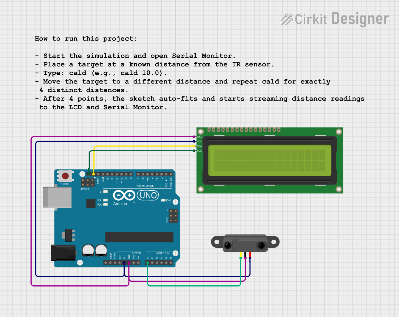
Circuit Documentation
Summary
This circuit is designed to utilize an Arduino UNO microcontroller to interface with an Infrared Proximity Sensor and a 16x2 I2C LCD display. The system is intended for distance measurement and calibration using the infrared sensor, with results displayed on the LCD. The Arduino processes the sensor data and provides a user interface through serial commands for calibration and status updates.
Component List
Arduino UNO
- Description: A microcontroller board based on the ATmega328P. It is used for programming and controlling the circuit.
- Purpose: Acts as the main controller for processing inputs from the infrared sensor and controlling the LCD display.
16x2 I2C LCD
- Description: A 16x2 character LCD that communicates via I2C protocol.
- Purpose: Displays information such as distance measurements and calibration status.
Infrared Proximity Sensor
- Description: A sensor that detects the presence of objects and measures distance using infrared light.
- Purpose: Provides distance measurements to the Arduino for processing and display.
Comment V2
- Description: A placeholder component with no electrical function in this circuit.
- Purpose: Not utilized in the circuit.
Wiring Details
Arduino UNO
5V: Connected to the Vcc pin of the Infrared Proximity Sensor and the VCC pin of the 16x2 I2C LCD.
GND: Connected to the GND pin of the Infrared Proximity Sensor and the GND pin of the 16x2 I2C LCD.
A0: Connected to the Vout pin of the Infrared Proximity Sensor.
SCL: Connected to the SCL pin of the 16x2 I2C LCD.
SDA: Connected to the SDA pin of the 16x2 I2C LCD.
16x2 I2C LCD
VCC: Connected to the 5V pin of the Arduino UNO.
GND: Connected to the GND pin of the Arduino UNO.
SCL: Connected to the SCL pin of the Arduino UNO.
SDA: Connected to the SDA pin of the Arduino UNO.
Infrared Proximity Sensor
Vcc: Connected to the 5V pin of the Arduino UNO.
GND: Connected to the GND pin of the Arduino UNO.
Vout: Connected to the A0 pin of the Arduino UNO.
Documented Code
Arduino Code
// IR Proximity Sensor 4-point calibration (model: d ≈ a/(V - V0) + b)
// LCD: I2C 16x2 at 0x27 (change to 0x3F if needed)
// Serial commands:
//   cald <cm>   (collect exactly 4 points at different distances)
//   status
//   help
//   reset

#include <Wire.h>
#include <LiquidCrystal_I2C.h>
#include <math.h>

LiquidCrystal_I2C lcd(0x27, 16, 2);   // change to 0x3F if your LCD differs

const uint8_t IR_PIN = A0;
const uint16_t ADC_MAX = 1023;
const float V_REF = 5.0f;              // UNO default analog reference

const uint8_t AVG_CAL    = 12;
const uint8_t AVG_STREAM = 8;
const unsigned long STREAM_MS = 200;

enum Stage { WAIT_POINTS, STREAMING };
Stage stage = WAIT_POINTS;

// 4 calibration points: store measured V and entered distance_cm
struct CalPoint { float V; float dist_cm; };
const int REQ_PTS = 4;
CalPoint pts[REQ_PTS];
int nPts = 0;

// Model parameters for d ~= a/(V - V0) + b
float a_par = 0.0f, b_par = 0.0f, V0_par = 0.0f;

unsigned long lastStream = 0;
String inLine;

int readADC(uint8_t samples) {
  long sum = 0;
  for (uint8_t i = 0; i < samples; i++) {
    sum += analogRead(IR_PIN);
    delay(2);
  }
  return (int)(sum / samples);
}

float adcToVoltage(int adc) {
  if (adc <= 0) return 0.0f;
  if (adc >= ADC_MAX) return V_REF;
  return (float)adc * (V_REF / ADC_MAX);
}

void sayNext(const __FlashStringHelper* msg) { Serial.print(F("NEXT: ")); Serial.println(msg); }
void sayNow (const __FlashStringHelper* msg) { Serial.print(F("DO THIS: ")); Serial.println(msg); }

// Linear regression for y = A*x + B
static bool fitLine(const float* x, const float* y, int n, float& A, float& B) {
  if (n < 2) return false;
  double Sx=0, Sy=0, Sxx=0, Sxy=0;
  for (int i=0;i<n;i++){ double xi=x[i], yi=y[i]; Sx+=xi; Sy+=yi; Sxx+=xi*xi; Sxy+=xi*yi; }
  double den = n*Sxx - Sx*Sx;
  if (fabs(den) < 1e-12) return false;
  A = (float)((n*Sxy - Sx*Sy)/den);
  B = (float)((Sy - A*Sx)/n);
  return true;
}

// Evaluate RMS error for a candidate V0 by linearizing x_i = 1/(V_i - V0) and fitting d = a*x + b
static bool tryV0(const CalPoint* p, int n, float V0, float& aOut, float& bOut, float& rms) {
  float x[REQ_PTS], y[REQ_PTS];
  for (int i=0;i<n;i++){
    float Vi = p[i].V;
    if (!(Vi > V0 + 1e-4f)) return false; // avoid division by near-zero or negative
    x[i] = 1.0f / (Vi - V0);
    y[i] = p[i].dist_cm;
  }
  float a,b;
  if (!fitLine(x, y, n, a, b)) return false;
  double err2=0.0;
  for (int i=0;i<n;i++){
    double di = (double)a * x[i] + b;
    double e = di - y[i];
    err2 += e*e;
  }
  rms = (float)sqrt(err2 / n);
  aOut = a; bOut = b;
  return true;
}

// Search V0 in a reasonable range to minimize RMS (coarse + refine)
bool fitNonlinearModel(const CalPoint* p, int n, float& a, float& b, float& V0) {
  if (n < 3) return false;

  // Define search bounds for V0. Use data-driven limits slightly below min(V) and near 0 V.
  float vmin = 10.0f, vmax = -1.0f;
  for (int i=0;i<n;i++){ vmin = min(vmin, p[i].V); vmax = max(vmax, p[i].V); }
  if (!(vmin < vmax)) return false;

  float lower = max(0.0f, vmin - 0.8f);   // allow an offset less than the smallest measured V
  float upper = min(vmin - 0.05f, V_REF*0.95f); // V0 must be at least 50 mV below min(V)
  if (!(upper > lower)) { // fallback generic range
    lower = 0.0f;
    upper = max(0.2f, vmin - 0.05f);
  }

  float bestA=0, bestB=0, bestV0=lower, bestRMS=1e9f;

  // Coarse grid
  const int N1 = 60;
  for (int i=0;i<=N1;i++){
    float v0 = lower + (upper - lower) * (float)i / (float)N1;
    float a1,b1,r1;
    if (tryV0(p, n, v0, a1, b1, r1)) {
      if (r1 < bestRMS) { bestRMS = r1; bestA=a1; bestB=b1; bestV0=v0; }
    }
  }

  // Refine around bestV0
  float span = (upper - lower) * 0.1f;
  float lo = max(0.0f, bestV0 - span);
  float hi = min(bestV0 + span, V_REF*0.98f);
  const int N2 = 80;
  for (int i=0;i<=N2;i++){
    float v0 = lo + (hi - lo) * (float)i / (float)N2;
    float a1,b1,r1;
    if