
Circuit Documentation
Summary of the Circuit
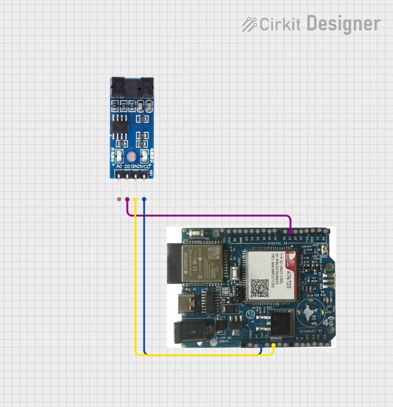
This circuit integrates an ESP32 with SIMCOM A7672s module and an LM393 comparator. The ESP32 module is responsible for processing data and communicating with the Blynk Cloud via the SIMCOM A7672s module, which provides cellular connectivity. The LM393 is used as a sensor input to the ESP32, which reads the sensor's digital output and sends this data to the Blynk Cloud for remote monitoring.
Component List
ESP32 with SIMCOM A7672s
- Description: A microcontroller module with integrated SIMCOM A7672s for cellular connectivity.
- Pins: SCA, SDA, NC, GND, 19, 23, 18, 25, 34, 33, 32, 27, 26, TX2, RX2, TX, 14, RX, 12, 13, 15, 2, 4, VIN, 5V, 3v3, IOREF
- Purpose: To process sensor data and communicate with the Blynk Cloud.
LM393
- Description: A dual differential comparator that provides a digital signal as an output.
- Pins: VCC, GND, D0, A0
- Purpose: To provide a digital signal to the ESP32 based on the analog input it compares.
Wiring Details
ESP32 with SIMCOM A7672s
- 27: Connected to LM393 D0
- GND: Common ground with LM393
- 3v3: Power supply to LM393 VCC
LM393
- D0: Connected to ESP32 GPIO 27
- GND: Common ground with ESP32
- VCC: Powered by ESP32 3v3 output
Documented Code
/* Written by Jacques Wilken
 * This sketch reads data from an LM393 sensor connected to an Lilygo T-SIM7000G ESP32 Module
 * and sends the data to Blynk Cloud using the SIMCOM A7672s module with TinyGSM.
 */

#define BLYNK_TEMPLATE_ID "TMPL2wMpNHE7e"
#define BLYNK_TEMPLATE_NAME "DHT11"
#define BLYNK_AUTH_TOKEN "2LPgcbcbnucoG9tmgXwAbykiGEXt5_b-"

// Select your modem:
#define TINY_GSM_MODEM_SIM7000   // SIMA7000 Compatible with SIM7000 AT instructions

#include <TinyGsmClient.h>
#include <BlynkSimpleTinyGSM.h>

// Set serial for debug console (to the Serial Monitor)
#define SerialMon Serial

// Set serial for AT commands (to the module)
#define SerialAT Serial1

// Your GPRS credentials
// Leave empty, if missing user or pass
const char apn[]  = "mymtn";
const char user[] = "";
const char pass[] = "";

// Pin definitions
const int lm393Pin = 27; // LM393 D0 connected to ESP32 GPIO 27

// Blynk auth token
char auth[] = BLYNK_AUTH_TOKEN;

TinyGsm modem(SerialAT);

void setup() {
  // Set console baud rate
  SerialMon.begin(115200);
  delay(10);

  // Set module baud rate
  SerialAT.begin(9600);
  delay(3000);

  // Restart takes quite some time
  // To skip it, call init() instead of restart()
  SerialMon.println("Initializing modem...");
  if (!modem.restart()) {
    SerialMon.println("Failed to restart modem, attempting to initialize...");
    if (!modem.init()) {
      SerialMon.println("Failed to initialize modem");
      while (true); // Halt execution
    }
  }

  // Unlock your SIM card with a PIN if needed
  // modem.simUnlock("1234");

  Blynk.begin(auth, modem, apn, user, pass);

  // Check if connected to Blynk
  if (!Blynk.connected()) {
    SerialMon.println("Failed to connect to Blynk");
    while (true); // Halt execution
  }

  // Initialize the LM393 pin
  pinMode(lm393Pin, INPUT);
}

void loop() {
  // Read the LM393 sensor value
  int sensorValue = digitalRead(lm393Pin);

  // Send the sensor value to Blynk
  Blynk.virtualWrite(V1, sensorValue);

  // Run Blynk
  Blynk.run();
}
This code is designed to be uploaded to the ESP32 with SIMCOM A7672s module. It initializes the modem, connects to the Blynk Cloud, and reads the digital output from the LM393 sensor. The sensor value is then sent to the Blynk Cloud for remote monitoring. The lm393Pin is defined as GPIO 27, which corresponds to the wiring between the ESP32 and the LM393.