
Circuit Documentation
Summary of the Circuit
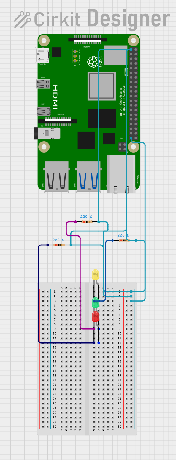
This circuit consists of a Raspberry Pi 4B microcontroller unit (MCU) and three LEDs (yellow, green, and red), each with an associated current-limiting resistor. The LEDs are connected to the Raspberry Pi via their anodes, while the cathodes are connected to the ground (GND) through the resistors. The Raspberry Pi provides a 3.3V power supply to the LEDs through the resistors, which are used to limit the current to a safe level for the LEDs.
Component List
Raspberry Pi 4B
- Description: A powerful microcontroller with multiple GPIO pins.
- Pins: 3V3, 5V, GPIOs, GND, and others.
- Purpose: Acts as the control unit for the circuit, providing power and potential GPIO control for the LEDs.
LED: Two Pin (yellow)
- Pins: Cathode, Anode
- Purpose: Emits yellow light when powered.
LED: Two Pin (green)
- Pins: Cathode, Anode
- Purpose: Emits green light when powered.
LED: Two Pin (red)
- Pins: Cathode, Anode
- Purpose: Emits red light when powered.
Resistor (220 Ohms)
- Pins: Pin1, Pin2
- Purpose: Limits the current flowing through the LEDs to prevent damage.
- Properties: 220 Ohms resistance.
Wiring Details
Raspberry Pi 4B
- 3V3: Provides power to the anodes of the LEDs through the resistors.
- GND: Connected to the cathodes of the LEDs through the resistors.
LED: Two Pin (yellow)
- Anode: Connected to the 3V3 power supply through a 220 Ohm resistor.
- Cathode: Connected to the GND of the Raspberry Pi.
LED: Two Pin (green)
- Anode: Connected to the 3V3 power supply through a 220 Ohm resistor.
- Cathode: Connected to the GND of the Raspberry Pi.
LED: Two Pin (red)
- Anode: Connected to the 3V3 power supply through a 220 Ohm resistor.
- Cathode: Connected to the GND of the Raspberry Pi.
Resistor (220 Ohms)
- Pin1: Connected to the anode of an LED.
- Pin2: Connected to the 3V3 power supply of the Raspberry Pi.
Documented Code
No code has been provided for the microcontroller in this circuit. If the Raspberry Pi is intended to control the LEDs via GPIO pins, the code would be necessary to define the behavior (e.g., blinking, brightness control) of the LEDs. Without the code, the LEDs will remain steadily lit as long as the Raspberry Pi is powered on.