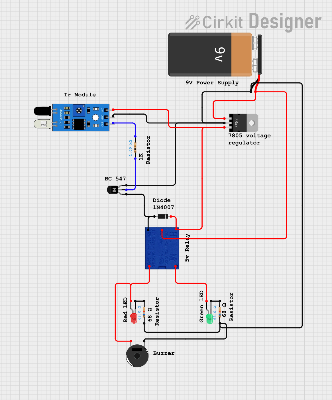
IR Sensor-Controlled Relay with Indicator LEDs and Buzzer Notification

Circuit Documentation
Summary
This circuit appears to be designed for controlling a relay based on the output of an infrared (IR) sensor, with visual indicators and a piezo buzzer for audible signaling. The circuit includes a voltage regulator to step down the voltage from a 9V battery to a lower voltage suitable for the IR sensor and the relay coil. An NPN transistor is used to drive the relay coil, which in turn switches the Normally Open (NO) and Normally Closed (NC) contacts. The relay contacts are used to control the power to a green LED (when NO) and a red LED with a piezo buzzer (when NC). The IR sensor output is conditioned by a resistor before being fed to the base of the NPN transistor. Diode protection is provided for the relay coil to prevent back EMF damage when the coil is de-energized.
Component List
Relay 5V
- A relay with a 5V coil voltage and contacts for common (COM), normally open (NO), and normally closed (NC).
- Pins: COM, COIL 1, COIL 2, NO, NC
Resistor
- A passive component used to limit current or divide voltages.
- Pins: pin1, pin2
- Values: 1000 Ohms, 68 Ohms (multiple instances with different resistance values)
IR Sensor
- A sensor that detects infrared light, typically used for proximity or motion detection.
- Pins: out, gnd, vcc
Voltage Regulator
- A device that maintains a constant output voltage regardless of changes in load current or input voltage.
- Pins: IN, GND, OUT
9V Battery
- A standard 9-volt battery used as the power source for the circuit.
- Pins: -, +
NPN Transistor (EBC)
- A bipolar junction transistor used for amplification and switching.
- Pins: emitter, base, collector
Diode
- A semiconductor device that allows current to flow in one direction only, used for protection against reverse polarity and voltage spikes.
- Pins: cathode, anode
Piezo Buzzer
- An electronic device that emits sound when an electrical signal is applied.
- Pins: pin 1, pin 2
LED: Two Pin (red)
- A red light-emitting diode used as a visual indicator.
- Pins: cathode, anode
LED: Two Pin (green)
- A green light-emitting diode used as a visual indicator.
- Pins: cathode, anode
Wiring Details
Relay 5V
- COIL 1 connected to the emitter of the NPN Transistor.
- COIL 2 connected to the Voltage Regulator OUT.
- COM connected to the Voltage Regulator IN.
- NO connected to the anode of the green LED.
- NC connected to the anode of the red LED and pin 2 of the Piezo Buzzer.
Resistor (1000 Ohms)
- pin1 connected to the base of the NPN Transistor.
- pin2 connected to the out pin of the IR Sensor.
Resistor (68 Ohms)
- pin1 connected to the cathode of the red LED.
- pin2 connected to the GND net, which includes the GND of the Voltage Regulator, Piezo Buzzer, NPN Transistor, IR Sensor, and the negative terminal of the 9V Battery.
IR Sensor
- out connected to pin2 of the 1000 Ohms Resistor.
- gnd connected to the GND net.
- vcc connected to the OUT of the Voltage Regulator.
Voltage Regulator
- IN connected to the positive terminal of the 9V Battery.
- GND connected to the GND net.
- OUT connected to the vcc of the IR Sensor and COIL 2 of the Relay.
9V Battery
- (negative) connected to the GND net.
- (positive) connected to the IN of the Voltage Regulator and COM of the Relay.
NPN Transistor (EBC)
- emitter connected to COIL 1 of the Relay.
- base connected to pin1 of the 1000 Ohms Resistor.
- collector connected to the GND net.
Diode
- cathode connected to the OUT of the Voltage Regulator.
- anode connected to COIL 1 of the Relay.
Piezo Buzzer
- pin 1 connected to the GND net.
- pin 2 connected to NC of the Relay.
LED: Two Pin (red)
- anode connected to NC of the Relay.
- cathode connected to pin1 of the 68 Ohms Resistor.
LED: Two Pin (green)
- anode connected to NO of the Relay.
- cathode connected to pin1 of the 68 Ohms Resistor.
Documented Code
There is no microcontroller code provided for this circuit. If the circuit is intended to be controlled by a microcontroller, the code would be necessary to define the behavior of the IR sensor output and the subsequent control of the relay and indicators. Without the code, the circuit is assumed to operate based on the direct output of the IR sensor.