
Circuit Documentation
Summary
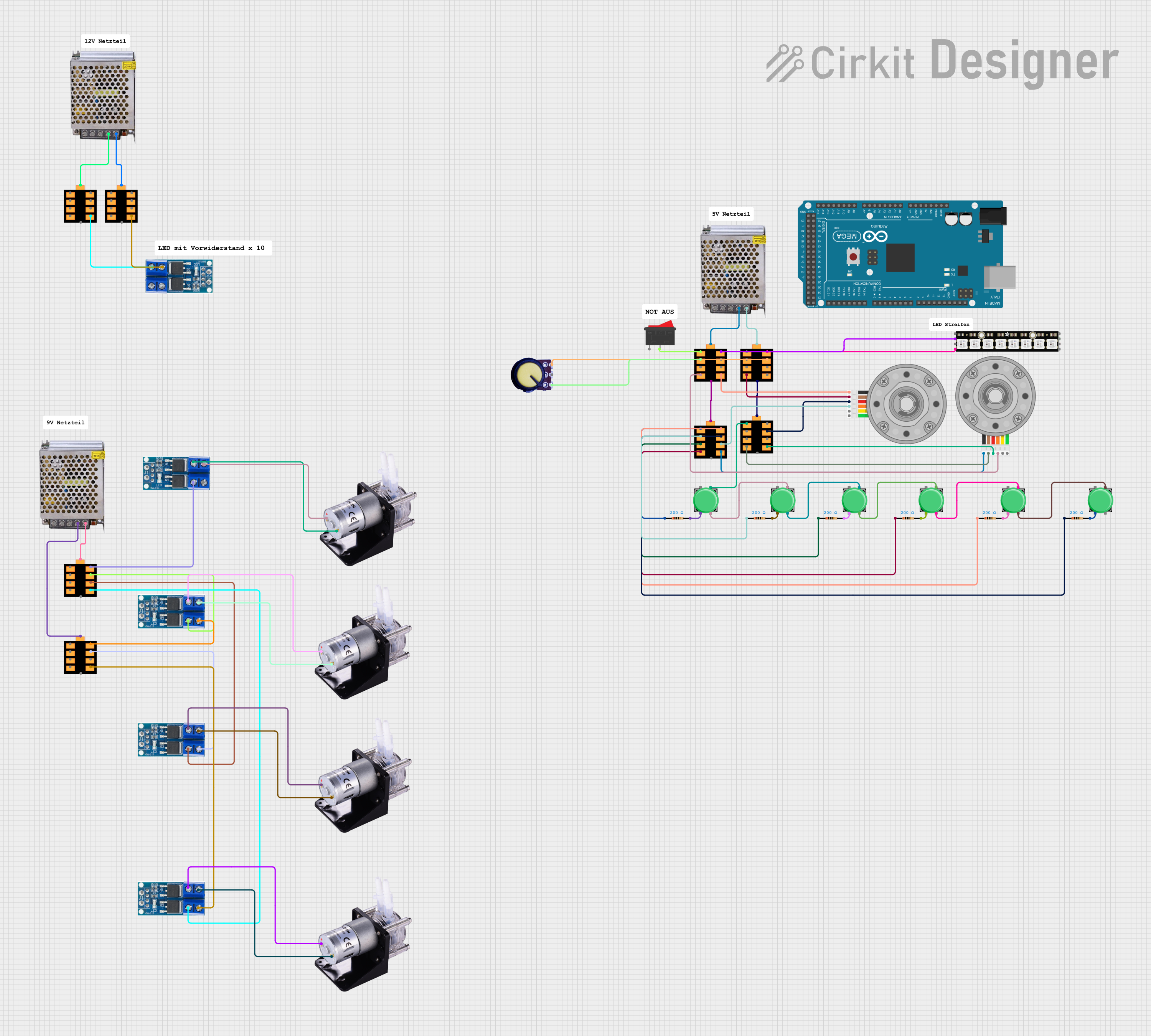
This document provides a comprehensive overview of a circuit designed to control peristaltic pumps, read inputs from pushbuttons and potentiometers, and drive DC motors with encoders. The circuit utilizes an Arduino Mega 2560 as the central microcontroller to manage the various components and execute the embedded code. The circuit also includes power distribution boards to manage power delivery to the components, power MOSFETs for controlling high-power devices, and various other components such as resistors, pushbuttons, and a NeoPixel LED stick for user interface and feedback.
Component List
Microcontroller
- Arduino Mega 2560: A microcontroller board based on the ATmega2560, with a wide range of input/output pins, including analog inputs, digital I/O pins, PWM outputs, and various communication interfaces.
Actuators
- Peristaltic Pump: A type of positive displacement pump used for pumping various fluids. The pump is controlled by power MOSFETs for on/off operation.
- DC Motor with Encoder: A motor that provides rotational movement with the added feature of an encoder for position feedback.
Power Management
- Power MOSFET: An electronic device used for switching or amplifying electronic signals in the circuit, typically used to control high-power devices like motors and pumps.
- Power Distribution Board: A board used for distributing power from a single input to multiple outputs.
- POWER SUPPLY 5V 5AMP: A power supply unit that provides a 5V DC output with a maximum current of 5A.
User Interface
- Pushbutton: A simple switch mechanism for controlling some aspect of a machine or a process. Multiple pushbuttons are used in this circuit for user inputs.
- Potentiometer: A three-terminal resistor with a rotating contact that forms an adjustable voltage divider. It is used for adjusting a parameter or as an input device.
- Rocker Switch: A switch that rocks back and forth, connecting either one of two circuits.
Feedback
- Adafruit NeoPixel Stick: An LED stick with multiple RGB LEDs that can be individually controlled to display various colors and patterns.
Passive Components
- Resistor: A passive two-terminal electrical component that implements electrical resistance as a circuit element. In this circuit, resistors are used for current limiting and pull-up configurations.
Wiring Details
Arduino Mega 2560
- Digital and analog I/O pins are used for interfacing with pushbuttons, potentiometers, and the NeoPixel stick.
- PWM outputs are connected to the gate pins of power MOSFETs for controlling the peristaltic pumps and DC motors.
Peristaltic Pumps
- Each pump has a positive and negative terminal. The positive terminal is connected to the drain of a power MOSFET, and the negative terminal is connected to the ground.
Power MOSFETs
- The gate of each MOSFET is controlled by a PWM output from the Arduino.
- The source of each MOSFET is connected to the ground, and the drain is connected to the positive terminal of a peristaltic pump or a DC motor.
Pushbuttons
- One side of each pushbutton is connected to a resistor, and the other side is chained to the next pushbutton or connected to the ground.
- The resistors are connected to a power distribution board output.
Potentiometer
- The middle pin (output) is connected to an analog input on the Arduino for reading the position.
- One of the outer pins is connected to the ground, and the other is connected to a power distribution board output.
Adafruit NeoPixel Stick
- The data input pin is connected to a digital output on the Arduino.
- The ground pin is connected to the ground, and the power pin is connected to a power distribution board output.
DC Motors with Encoders
- The motor terminals are connected to the power distribution board outputs.
- The encoder outputs are connected to the Arduino for position feedback.
Power Distribution Boards
- Each board's input is connected to a 5V power supply output.
- The outputs are connected to various components such as pushbuttons, potentiometers, NeoPixel sticks, and motors.
Resistors
- Each resistor is connected in series with a pushbutton and to a power distribution board output.
Documented Code
Arduino Mega 2560
sketch.ino
void setup() {
  // put your setup code here, to run once:

}

void loop() {
  // put your main code here, to run repeatedly:

}
documentation.txt
(No additional documentation provided for the code)
This concludes the documentation for the circuit. The provided information outlines the purpose and connection details for each component, as well as the basic structure of the embedded code to be run on the Arduino Mega 2560.