
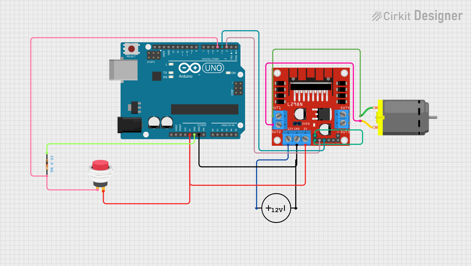
Circuit Documentation
Summary
This circuit is designed to control a DC motor using an Arduino UNO and an L298N motor driver. The motor is powered by a DC power source, and its operation is controlled via a push switch. The Arduino UNO is programmed to manage the motor's direction and speed based on the input from the push switch.
Component List
DC Power Source
- Description: Provides the necessary voltage and current to power the motor and other components.
- Pins: Ground, Positive
DC Motor
- Description: Converts electrical energy into mechanical motion.
- Pins: pin 1, pin 2
Arduino UNO
- Description: A microcontroller board used for controlling the motor and reading the push switch input.
- Pins: UNUSED, IOREF, Reset, 3.3V, 5V, GND, Vin, A0, A1, A2, A3, A4, A5, SCL, SDA, AREF, D13, D12, D11, D10, D9, D8, D7, D6, D5, D4, D3, D2, D1, D0
L298N DC Motor Driver
- Description: A dual H-bridge motor driver that allows control of the motor's direction and speed.
- Pins: OUT1, OUT2, 12V, GND, 5V, OUT3, OUT4, 5V-ENA-JMP-I, 5V-ENA-JMP-O, +5V-J1, +5V-J2, ENA, IN1, IN2, IN3, IN4, ENB
Resistor
- Description: Limits the current flow in the circuit.
- Pins: pin1, pin2
- Properties: Resistance: 10000 Ohms
2Pin Push Switch
- Description: A switch used to control the motor operation.
- Pins: Input +, Output +
Wiring Details
DC Power Source
- Positive is connected to 12V on the L298N DC Motor Driver.
- Ground is connected to GND on the L298N DC Motor Driver and GND on the Arduino UNO.
DC Motor
- pin 1 is connected to OUT1 on the L298N DC Motor Driver.
- pin 2 is connected to OUT2 on the L298N DC Motor Driver.
Arduino UNO
- GND is connected to Ground on the DC Power Source and GND on the L298N DC Motor Driver.
- 5V is connected to Output + on the 2Pin Push Switch and 5V on the L298N DC Motor Driver.
- D2 is connected to IN1 on the L298N DC Motor Driver.
- D3 is connected to IN2 on the L298N DC Motor Driver.
- D4 is connected to Input + on the 2Pin Push Switch and pin2 on the Resistor.
L298N DC Motor Driver
- OUT1 is connected to pin 1 on the DC Motor.
- OUT2 is connected to pin 2 on the DC Motor.
- 12V is connected to Positive on the DC Power Source.
- GND is connected to Ground on the DC Power Source and GND on the Arduino UNO.
- 5V is connected to Output + on the 2Pin Push Switch and 5V on the Arduino UNO.
- 5V-ENA-JMP-I is connected to 5V-ENA-JMP-O on the L298N DC Motor Driver.
- ENA is connected to +5V-J1 on the L298N DC Motor Driver.
- IN1 is connected to D2 on the Arduino UNO.
- IN2 is connected to D3 on the Arduino UNO.
Resistor
- pin1 is connected to GND on the Arduino UNO.
- pin2 is connected to Input + on the 2Pin Push Switch and D4 on the Arduino UNO.
2Pin Push Switch
- Input + is connected to D4 on the Arduino UNO and pin2 on the Resistor.
- Output + is connected to 5V on the Arduino UNO and 5V on the L298N DC Motor Driver.
Code Documentation
Arduino UNO Code
int motor1pin1 = 2;
int motor1pin2 = 3;
int buttonpin = 4;

void setup() {
  Serial.begin(9600);
  pinMode(motor1pin1, OUTPUT);
  pinMode(motor1pin2, OUTPUT);
  pinMode(buttonpin, INPUT);
}

#define TIME4_1_METER  550  //CHANGE FOR CALIBRATION
#define DISTANCE_CM   600

void loop() {
  while (digitalRead(buttonpin) == false) {
    delay(20);
  }
  digitalWrite(motor1pin1, HIGH);
  digitalWrite(motor1pin2, LOW);

  int travel_time = (7 * DISTANCE_CM) + 200;
  Serial.println(travel_time);
  delay(travel_time);

  digitalWrite(motor1pin1, LOW);
  digitalWrite(motor1pin2, LOW);
}
This code initializes the pins for the motor and the push switch. In the setup function, the serial communication is started, and the pin modes are set. The loop function waits for the push switch to be pressed, then runs the motor for a calculated travel time, and finally stops the motor.