
Arduino-Controlled Dual DC Motor Driver with IR and Ultrasonic Sensors
View and Edit Project In Cirkit Designer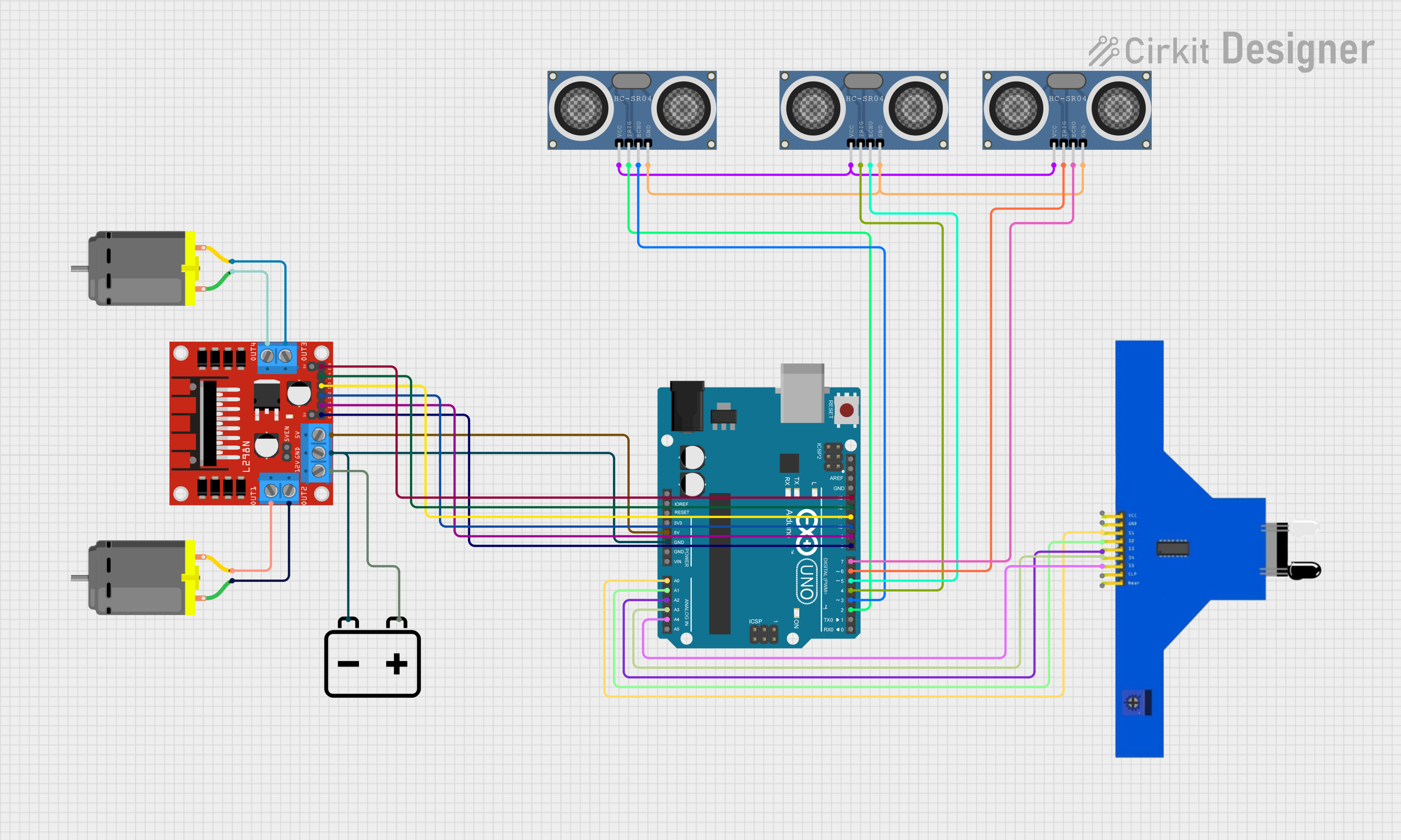
Circuit Documentation
Summary
This circuit is designed to control two DC motors using an L298N DC motor driver, which is interfaced with an Arduino UNO microcontroller. The circuit also includes three HC-SR04 Ultrasonic Distance Sensors for distance measurement and a 5 channel IR sensor for line tracking or obstacle detection. The entire system is powered by a 12V battery, which supplies power to the motor driver and, through a voltage regulator on the driver board, to the Arduino UNO.
Component List
5 Channel IR Sensor
- Pins: VCC, GND, S1, S2, S3, S4, S5, CLP, Near
- Description: This sensor is used for line tracking or obstacle detection with five IR sensors.
DC Motor (x2)
- Pins: pin 1, pin 2
- Description: These motors are the actuators in the circuit, responsible for converting electrical energy into mechanical motion.
L298N DC Motor Driver
- Pins: OUT1, OUT2, 12V, GND, 5V, OUT3, OUT4, 5V-ENA-JMP-I, 5V-ENA-JMP-O, +5V-J1, +5V-J2, ENA, IN1, IN2, IN3, IN4, ENB
- Description: This component is an H-bridge motor driver that allows for the control of two DC motors' speed and direction.
Arduino UNO
- Pins: UNUSED, IOREF, Reset, 3.3V, 5V, GND, Vin, A0, A1, A2, A3, A4, A5, SCL, SDA, AREF, D13, D12, D11, D10, D9, D8, D7, D6, D5, D4, D3, D2, D1, D0
- Description: The Arduino UNO is the main microcontroller board in the circuit, responsible for processing inputs and controlling outputs.
HC-SR04 Ultrasonic Distance Sensor (Wokwi Compatible) (x3)
- Pins: VCC, TRIG, ECHO, GND
- Description: These sensors are used to measure distances by emitting ultrasonic waves and measuring the time taken for the echo to return.
12V Battery
- Pins: -, +
- Description: This is the power source for the circuit, providing the necessary voltage to drive the motors and the motor driver.
Wiring Details
5 Channel IR Sensor
- VCC: Connected to 5V power supply
- GND: Connected to ground
- S1 - S5: Connected to analog inputs A0 - A4 on the Arduino UNO for sensor readings
DC Motors
- Motor 1:
- pin 1: Connected to OUT2 on the L298N motor driver
- pin 2: Connected to OUT1 on the L298N motor driver
- Motor 2:
- pin 1: Connected to OUT4 on the L298N motor driver
- pin 2: Connected to OUT3 on the L298N motor driver
L298N DC Motor Driver
- 12V: Connected to the + terminal of the 12V battery
- GND: Connected to the - terminal of the 12V battery and to the GND on the Arduino UNO
- 5V: Connected to the 5V pin on the Arduino UNO to power the logic circuitry
- ENA, ENB: Connected to digital pins D8 and D13 on the Arduino UNO for enabling the motor outputs
- IN1 - IN4: Connected to digital pins D9 - D12 on the Arduino UNO for controlling motor direction
Arduino UNO
- 5V: Connected to the 5V output from the L298N motor driver
- GND: Connected to the ground of the L298N motor driver and the 12V battery
- Digital pins D2 - D13: Used for controlling the motor driver and reading from the ultrasonic sensors
- Analog pins A0 - A4: Used for reading from the 5 channel IR sensor
HC-SR04 Ultrasonic Distance Sensors
- All VCC pins: Connected together and to a 5V power supply
- All GND pins: Connected together and to ground
- TRIG and ECHO pins: Connected to various digital pins on the Arduino UNO for triggering and reading the distance
12V Battery
- +: Connected to the 12V input on the L298N motor driver
- -: Connected to the ground of the L298N motor driver
Documented Code
void setup() {
  // put your setup code here, to run once:

}

void loop() {
  // put your main code here, to run repeatedly:

}
The provided code is a template for the Arduino UNO microcontroller. The setup() function is called once when the microcontroller is powered on or reset. It is used to initialize variables, pin modes, start using libraries, etc. The loop() function is called repeatedly and contains the main logic of the code. It controls the motor driver, reads sensor data, and implements the control logic for the circuit's operation.