ESP32-Based Data Display and RF Communication System
Circuit Documentation
Summary
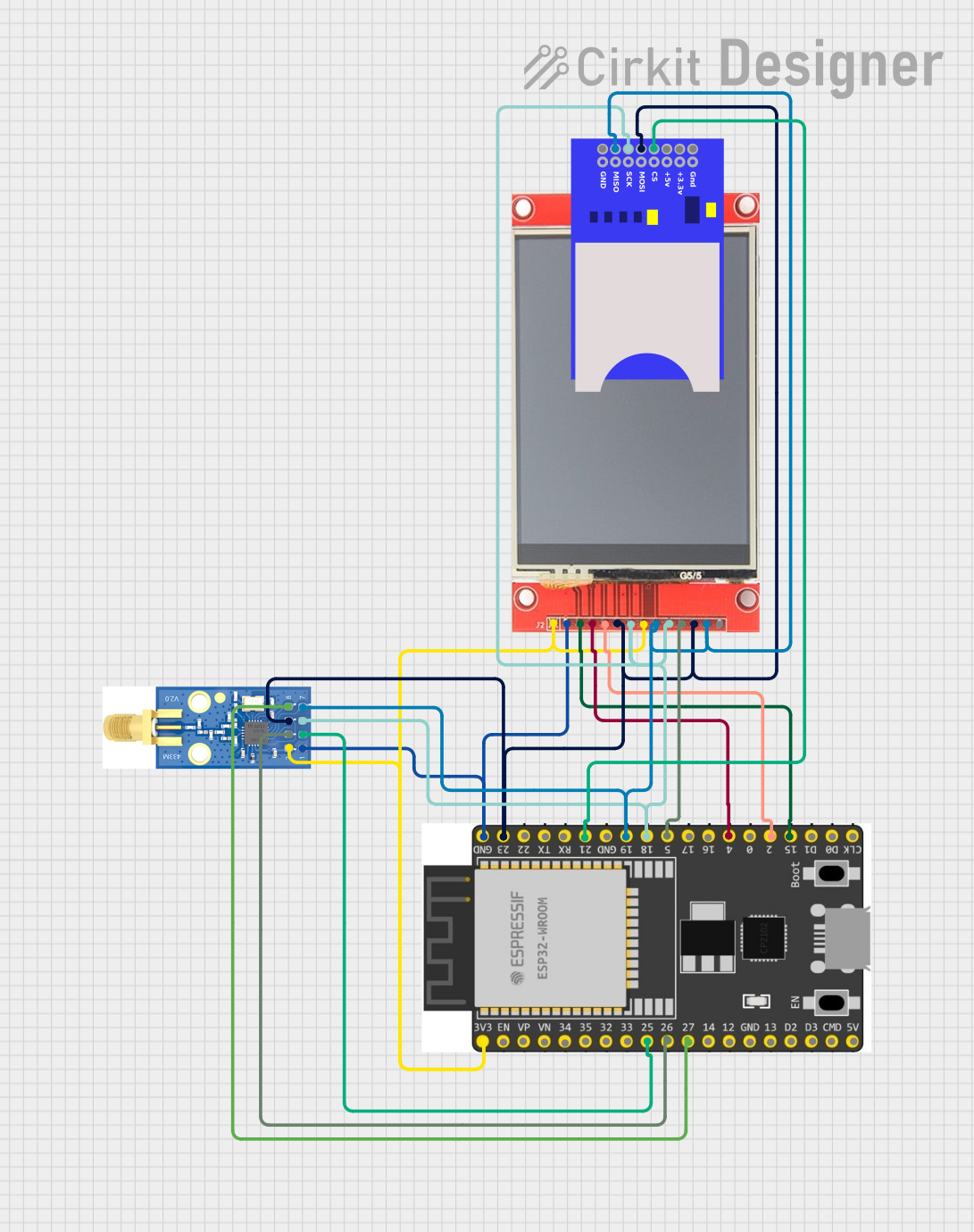
The circuit in question is designed to interface an ESP32 Wroom Dev Kit microcontroller with several peripheral devices: an ili9341 TFT display, an SD card module, and an E07-M1101D transceiver module. The ESP32 serves as the central processing unit, controlling the display, managing data storage via the SD card, and handling wireless communication through the E07-M1101D module. The circuit is powered through the ESP32's 3.3V output, which also powers the other components. Ground connections are shared across all devices to complete the circuit.
Component List
ESP32 Wroom Dev Kit
- Microcontroller with WiFi and Bluetooth capabilities.
- It has a variety of GPIO pins for interfacing with other devices and sensors.
ili9341 TFT Display
- A color graphic display with a resolution of 240x320 pixels.
- It uses SPI for communication and has additional pins for control signals.
SD Card Module
- A module that allows the microcontroller to read from and write to SD cards.
- It uses SPI for communication with the microcontroller.
E07-M1101D
- A wireless transceiver module for communication over the 433MHz band.
- It also uses SPI for communication with the microcontroller.
Wiring Details
ESP32 Wroom Dev Kit
3V3- Powers the ili9341 TFT display, its backlight (LED), and the E07-M1101D module.GND- Common ground for the ili9341 TFT display and the E07-M1101D module.GPIO 15- Connected to the CS pin of the ili9341 TFT display for SPI communication.GPIO 4- Connected to the RESET pin of the ili9341 TFT display.GPIO 2- Connected to the DC/RS pin of the ili9341 TFT display for SPI communication.GPIO 23- Serves as the MOSI line for SPI communication with the SD card module, the ili9341 TFT display, and the E07-M1101D module.GPIO 18- Serves as the SCK line for SPI communication with the SD card module, the ili9341 TFT display, and the E07-M1101D module.GPIO 19- Serves as the MISO line for SPI communication with the SD card module, the ili9341 TFT display, and the E07-M1101D module.GPIO 5- Connected to the T_CS pin of the ili9341 TFT display for touch control.GPIO 25- Connected to the GDO0 pin of the E07-M1101D module.GPIO 26- Connected to the CSN pin of the E07-M1101D module for SPI communication.GPIO 27- Connected to the GDO2 pin of the E07-M1101D module.GPIO 21- Connected to the CS pin of the SD card module for SPI communication.
ili9341 TFT Display
VCC- Powered by the 3.3V output from the ESP32.GND- Connected to the common ground.CS- Chip select for SPI communication, controlled by GPIO 15 of the ESP32.RESET- Reset pin, controlled by GPIO 4 of the ESP32.DC/RS- Data/command control pin, controlled by GPIO 2 of the ESP32.SDI- SPI data input, connected to GPIO 23 (MOSI) of the ESP32.SCK- SPI clock, connected to GPIO 18 (SCK) of the ESP32.LED- Backlight control, powered by the 3.3V output from the ESP32.SDO- SPI data output, connected to GPIO 19 (MISO) of the ESP32.T_CS- Touch panel chip select, controlled by GPIO 5 of the ESP32.
SD Card Module
GND- Connected to the common ground.+3.3V- Powered by the 3.3V output from the ESP32.CS- Chip select for SPI communication, controlled by GPIO 21 of the ESP32.MOSI- SPI data input, connected to GPIO 23 (MOSI) of the ESP32.SCK- SPI clock, connected to GPIO 18 (SCK) of the ESP32.MISO- SPI data output, connected to GPIO 19 (MISO) of the ESP32.
E07-M1101D
GND- Connected to the common ground.VCC- Powered by the 3.3V output from the ESP32.GDO0- Digital output, connected to GPIO 25 of the ESP32.CSN- Chip select for SPI communication, controlled by GPIO 26 of the ESP32.SCK- SPI clock, connected to GPIO 18 (SCK) of the ESP32.MOSI- SPI data input, connected to GPIO 23 (MOSI) of the ESP32.MISO/GDO1- SPI data output, connected to GPIO 19 (MISO) of the ESP32.GDO2- Digital output, connected to GPIO 27 of the ESP32.
Documented Code
Since no code was provided in the input, this section is left blank. Normally, this section would include the source code for the microcontroller, along with comments explaining the functionality of each part of the code. It would also detail how the code interacts with the hardware components listed above, including initialization of peripherals, main program loop, interrupt service routines, and any power management features.