Cirkit Designer
Your all-in-one circuit design IDE
Home /
Project Documentation
Adjustable Brightness LED Circuit with Pushbutton Control

Circuit Documentation
Summary of the Circuit
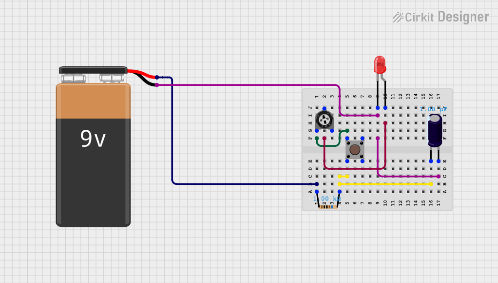
This circuit appears to be a simple electronic system that includes a power source, a resistor, a trimmer potentiometer, a pushbutton, an LED, and an electrolytic capacitor. The circuit's functionality seems to be centered around the LED, which can be turned on and off using the pushbutton and whose brightness can be adjusted using the trimmer potentiometer. The resistor limits the current to the LED, and the capacitor may be used for smoothing any voltage spikes when the pushbutton is pressed.
Component List
Trimmer Potentiometer
- Description: A variable resistor with three terminals called leg1, wiper, and leg2.
- Properties:
- Resistance: 10,000 Ohms
LED: Two Pin (red)
- Description: A red light-emitting diode with two terminals called cathode and anode.
Electrolytic Capacitor
- Description: A capacitor with two terminals marked as negative (-) and positive (+).
- Properties:
- Capacitance: 1 microfarad (0.000001 Farads)
Pushbutton
- Description: A momentary switch with four terminals, two marked as Pin 1 (in) and Pin 2 (in) for the input side, and two marked as Pin 3 (out) and Pin 4 (out) for the output side.
9V Battery
- Description: A standard 9-volt battery with two terminals marked as negative (-) and positive (+).
Resistor
- Description: A passive two-terminal electrical component that implements electrical resistance.
- Properties:
- Resistance: 1,000 Ohms
Wiring Details
Trimmer Potentiometer
- Leg1: Connected to Pushbutton Pin 1 (in)
- Wiper: Connected to LED Anode
- Leg2: Not connected in the provided net list
LED: Two Pin (red)
- Anode: Connected to Trimmer Potentiometer Wiper
- Cathode: Connected to Electrolytic Capacitor Negative (-) and 9V Battery Negative (-)
Electrolytic Capacitor
- Negative (-): Connected to LED Cathode and 9V Battery Negative (-)
- Positive (+): Connected to Pushbutton Pin 2 (in)
Pushbutton
- Pin 1 (in): Connected to Trimmer Potentiometer Leg1
- Pin 2 (in): Connected to Electrolytic Capacitor Positive (+)
- Pin 3 (out): Not connected in the provided net list
- Pin 4 (out): Not connected in the provided net list
9V Battery
- Positive (+): Connected to Resistor Pin1
- Negative (-): Connected to LED Cathode and Electrolytic Capacitor Negative (-)
Resistor
- Pin1: Connected to 9V Battery Positive (+)
- Pin2: Connected to Electrolytic Capacitor Negative (-) and Pushbutton Pin 2 (in)
Documented Code
There is no code provided for any microcontrollers in the circuit. If the circuit is later updated to include a microcontroller, the code will be documented in this section.