
Circuit Documentation
Summary
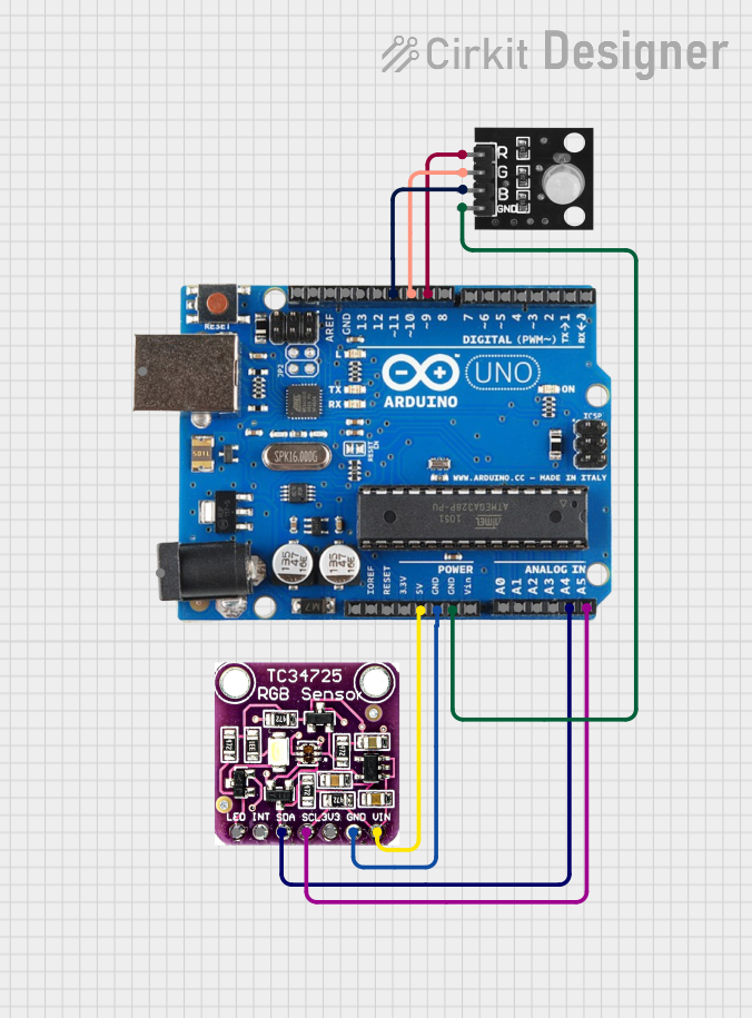
This circuit consists of an Arduino Uno R3 microcontroller, a TCS3472 color light-to-digital converter with an IR filter, and an RGB LED module. The Arduino Uno R3 reads color data from the TCS3472 sensor and uses this data to control the color of the RGB LED.
Component List
Arduino Uno R3
- Description: A microcontroller board based on the ATmega328P.
- Pins: D8, D9, D10, D11, D12, D13, GND, AREF, SDA, SCL, D0/RX, D1/Tx, D2, D3, D4, D5, 6, D7, A5/SCL, A4/SDA, A3, A2, A1, A0, Vin, 5V, 3.3V, RESET, IOREF, NONE, USB Jack, Power Jack.
TCS3472 COLOR LIGHT-TO-DIGITAL CONVERTER with IR FILTER
- Description: A color sensor that converts light to digital values.
- Pins: LED, INT, SDA, SCL, 3V3, GND, VIN.
RGB LED Module
- Description: An LED module with red, green, and blue LEDs.
- Pins: +VCC Red, +VCC Green, +VCC Blue, GND.
Wiring Details
Arduino Uno R3
- D9: Connected to +VCC Red of RGB LED module.
- D10: Connected to +VCC Green of RGB LED module.
- D11: Connected to +VCC Blue of RGB LED module.
- A5/SCL: Connected to SCL of TCS3472 color sensor.
- A4/SDA: Connected to SDA of TCS3472 color sensor.
- GND: Connected to GND of RGB LED module and GND of TCS3472 color sensor.
- 5V: Connected to VIN of TCS3472 color sensor.
TCS3472 COLOR LIGHT-TO-DIGITAL CONVERTER with IR FILTER
- SCL: Connected to A5/SCL of Arduino Uno R3.
- SDA: Connected to A4/SDA of Arduino Uno R3.
- GND: Connected to GND of Arduino Uno R3.
- VIN: Connected to 5V of Arduino Uno R3.
RGB LED Module
- +VCC Red: Connected to D9 of Arduino Uno R3.
- +VCC Green: Connected to D10 of Arduino Uno R3.
- +VCC Blue: Connected to D11 of Arduino Uno R3.
- GND: Connected to GND of Arduino Uno R3.
Code Documentation
Arduino Code
#include <Wire.h>
#include <Adafruit_TCS34725.h>

#define RED_PIN 9
#define GREEN_PIN 10
#define BLUE_PIN 11

// Initialize the TCS34725 color sensor
Adafruit_TCS34725 tcs = Adafruit_TCS34725(TCS34725_INTEGRATIONTIME_50MS, TCS34725_GAIN_4X);

void setup() {
  // Initialize Serial Monitor
  Serial.begin(9600);

  // Initialize color sensor
  if (!tcs.begin()) {
    Serial.println("Couldn't find TCS34725 sensor!");
    while (1);
  }

  // Initialize RGB LED pins
  pinMode(RED_PIN, OUTPUT);
  pinMode(GREEN_PIN, OUTPUT);
  pinMode(BLUE_PIN, OUTPUT);
}

void loop() {
  uint16_t r, g, b, c;

  // Get RGB color values from the sensor
  tcs.getRawData(&r, &g, &b, &c);

  // Map the raw sensor values to an 8-bit range (0-255)
  int red = map(r, 0, 65535, 0, 255);
  int green = map(g, 0, 65535, 0, 255);
  int blue = map(b, 0, 65535, 0, 255);

  // Print RGB values to Serial Monitor
  Serial.print("R: "); Serial.print(red);
  Serial.print(" G: "); Serial.print(green);
  Serial.print(" B: "); Serial.println(blue);

  // Set RGB LED color
  analogWrite(RED_PIN, red);
  analogWrite(GREEN_PIN, green);
  analogWrite(BLUE_PIN, blue);

  // Delay for a moment
  delay(1000);
}
This code initializes the TCS34725 color sensor and reads RGB values from it. These values are then used to set the color of the RGB LED module. The RGB values are also printed to the Serial Monitor for debugging purposes.