
Arduino Nano-Controlled Robotic Platform with Bluetooth and Motion Sensing
View and Edit Project In Cirkit Designer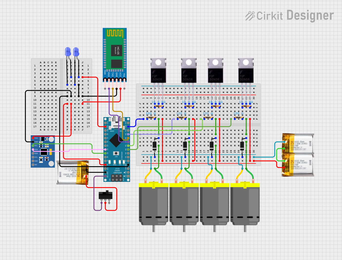
Circuit Documentation
Summary of the Circuit
This circuit appears to be a microcontroller-based system designed to control multiple DC motors, possibly for a robotics or automation application. It includes an Arduino Nano as the central processing unit, interfaced with an HC-05 Bluetooth module for wireless communication and an MPU6050 accelerometer and gyroscope for motion sensing. The circuit is powered by 3.7v LiPo batteries and includes MOSFETs for motor control, diodes for flyback protection, and resistors for various purposes including pull-downs for the MOSFET gates. There are also LEDs for indication purposes and a toggle switch to control the power supply to the Arduino Nano.
Component List
Microcontroller
- Arduino Nano: A compact microcontroller board based on the ATmega328P, featuring digital and analog I/O pins.
Power Supply
- 3.7v LiPo Battery: A rechargeable lithium polymer battery providing the power source for the circuit.
Communication Module
- HC-05 Bluetooth Module: A wireless communication module that allows Bluetooth connectivity.
Sensors
- MPU6050 Accelerometer + Gyroscope: A motion tracking device that combines a 3-axis gyroscope and a 3-axis accelerometer.
Actuators
- DC Motor: An electric motor that converts electrical energy into mechanical rotation.
Switches
- Toggle Switch: A switch that can maintain its state either in on or off positions.
Indicators
- LED (blue): A light-emitting diode used as an indicator light.
Protection
- Diode: A component that allows current to flow in one direction, used here for flyback protection in motor driving circuits.
Control
- Mosfet: A type of transistor used for switching electronic signals, in this case, used to control the DC motors.
Resistors
- Resistor (10k Ohms): A component that provides resistance in the circuit, used for pull-downs on the MOSFET gates.
- Resistor (100 Ohms): A lower resistance used possibly for current limiting or voltage division.
Wiring Details
Arduino Nano
- Digital and analog pins are used for interfacing with sensors, communication modules, and controlling MOSFETs.
- The
VINpin is connected to a toggle switch for power control. - The
GNDpin is connected to the common ground of the circuit. - The
5Vpin provides power to the MPU6050 and HC-05 Bluetooth module. - The
3V3pin powers the blue LEDs.
3.7v LiPo Battery
- The
+Vepin is connected to the motors, MOSFETs, and the common positive rail of the circuit. - The
GNDpin is connected to the common ground.
HC-05 Bluetooth Module
RXDandTXDpins are connected to the Arduino Nano for serial communication.VCCandGNDpins are connected to the Arduino Nano's5VandGNDpins for power.
MPU6050 Accelerometer + Gyroscope
SCLandSDApins are connected to the Arduino Nano for I2C communication.VCCandGNDpins are connected to the Arduino Nano's5VandGNDpins for power.
DC Motor
- One pin of each motor is connected to the drain of a corresponding MOSFET.
- The other pin of each motor is connected to the positive rail of the battery through diodes.
Diode
- Anodes are connected to the drains of MOSFETs and one pin of the motors.
- Cathodes are connected together and to the positive rail of the battery.
Mosfet
- Gates are connected to digital pins of the Arduino Nano through resistors.
- Drains are connected to the anodes of diodes and one pin of the motors.
- Sources are connected to the common ground.
Resistor (10k Ohms)
- One end is connected to the gate of a MOSFET, and the other end is connected to the ground.
Resistor (100 Ohms)
- Used in the gate circuitry of MOSFETs, possibly for current limiting.
Toggle Switch
- Connected between the
VINpin of the Arduino Nano and the positive rail of the battery.
LED (blue)
- Anodes are connected to the
3V3pin of the Arduino Nano. - Cathodes are connected to the common ground.
Documented Code
void setup() {
  // put your setup code here, to run once:

}

void loop() {
  // put your main code here, to run repeatedly:

}
The provided code is a template with empty setup() and loop() functions, which are the standard structure for Arduino sketches. The setup() function is intended to contain initialization code that runs once when the microcontroller is powered on or reset. The loop() function is for code that runs continuously as long as the microcontroller is powered. Actual implementation details need to be added to these functions based on the specific requirements of the circuit's operation.