
Arduino-Based RFID Controlled Solenoid Lock with LED Indicators
View and Edit Project In Cirkit Designer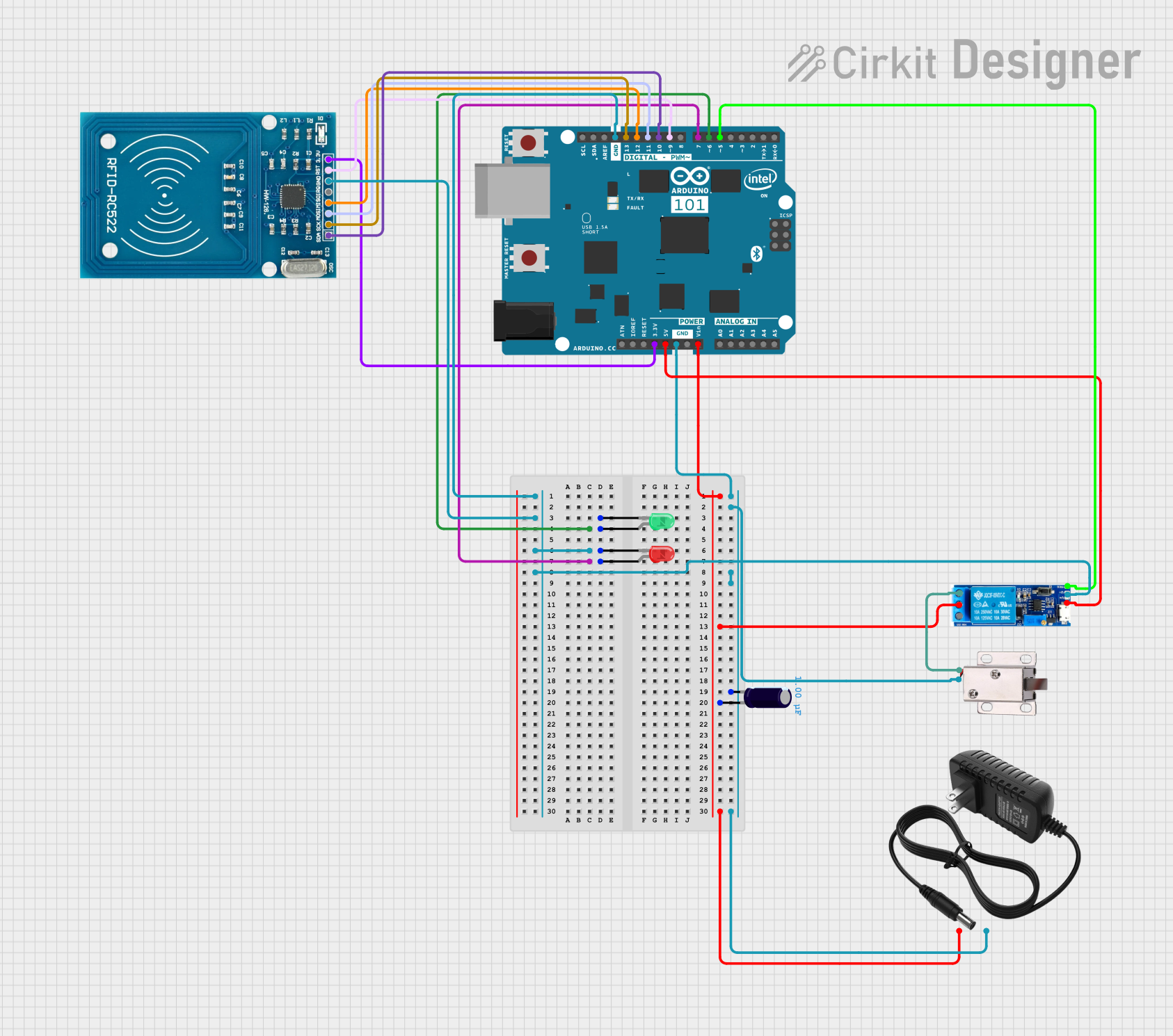
Circuit Documentation
Summary
This circuit is designed to control a 12V solenoid lock using an Arduino 101 microcontroller, an RFID-RC522 module for authentication, and a relay module to switch the solenoid lock. The circuit also includes two LEDs (red and green) to indicate the status of the lock. The entire system is powered by a 12V power supply, with an electrolytic capacitor for voltage stabilization.
Component List
Relay module 5v-30v
- Pins: common contact, normally open, normally closed, trigger, V-, V+
- Description: A relay module used to switch the 12V solenoid lock.
- Purpose in Circuit: To control the power to the solenoid lock based on the Arduino's signal.
12V solenoid lock
- Pins: VCC, GND
- Description: A solenoid lock that operates at 12V.
- Purpose in Circuit: To lock or unlock based on the relay's state.
12v power supply
- Pins: +, -
- Description: A power supply providing 12V DC.
- Purpose in Circuit: To power the solenoid lock and other components.
LED: Two Pin (red)
- Pins: cathode, anode
- Description: A red LED.
- Purpose in Circuit: To indicate the status of the lock.
LED: Two Pin (green)
- Pins: cathode, anode
- Description: A green LED.
- Purpose in Circuit: To indicate the status of the lock.
Arduino 101
- Pins: A5/SCL, A4/SDA, AREF, GND, D13/SCK, D12/MISO, D11 PWM/MOSI, D10 PWM/SS, D9 PWM, D8, D7, D6 PWM, D5 PWM, D4, D3 PWM, D2, D1/TX, D0/RX, AIN, ioref, RESET, 3V3, 5V, VIN, A0, A1, A2, A3, ICSP MISO, ICSP SCK, ICSP MOSI
- Description: A microcontroller board.
- Purpose in Circuit: To control the relay and read the RFID module.
RFID-RC522
- Pins: VCC (3.3V), RST, GND, IRQ, MISO, MOSI, SCK, SDA
- Description: An RFID reader module.
- Purpose in Circuit: To read RFID tags for authentication.
Electrolytic Capacitor
- Pins: -, +
- Description: A capacitor with a capacitance of 1µF.
- Purpose in Circuit: To stabilize the voltage supply.
Wiring Details
Relay module 5v-30v
- common contact: Connected to the + pin of the 12v power supply and the + pin of the electrolytic capacitor.
- normally open: Connected to the VCC pin of the 12V solenoid lock.
- trigger: Connected to the D5 PWM pin of the Arduino 101.
- V-: Connected to the GND pin of the Arduino 101, the GND pin of the RFID-RC522, and the cathode pin of the red LED.
- V+: Connected to the 5V pin of the Arduino 101.
12V solenoid lock
- VCC: Connected to the normally open pin of the relay module.
- GND: Connected to the - pin of the 12v power supply and the - pin of the electrolytic capacitor.
12v power supply
- +: Connected to the common contact pin of the relay module and the + pin of the electrolytic capacitor.
- -: Connected to the GND pin of the Arduino 101, the - pin of the electrolytic capacitor, and the GND pin of the 12V solenoid lock.
LED: Two Pin (red)
- cathode: Connected to the GND pin of the Arduino 101, the GND pin of the RFID-RC522, and the V- pin of the relay module.
- anode: Connected to the D7 pin of the Arduino 101.
LED: Two Pin (green)
- cathode: Not connected.
- anode: Connected to the D6 PWM pin of the Arduino 101.
Arduino 101
- VIN: Connected to the + pin of the electrolytic capacitor and the common contact pin of the relay module.
- GND: Connected to the - pin of the electrolytic capacitor, the - pin of the 12v power supply, the GND pin of the 12V solenoid lock, the GND pin of the RFID-RC522, and the cathode pin of the red LED.
- D5 PWM: Connected to the trigger pin of the relay module.
- D6 PWM: Connected to the anode pin of the green LED.
- D7: Connected to the anode pin of the red LED.
- 3V3: Connected to the VCC (3.3V) pin of the RFID-RC522.
- D9 PWM: Connected to the RST pin of the RFID-RC522.
- D10 PWM/SS: Connected to the SDA pin of the RFID-RC522.
- D11 PWM/MOSI: Connected to the MOSI pin of the RFID-RC522.
- D12/MISO: Connected to the MISO pin of the RFID-RC522.
- D13/SCK: Connected to the SCK pin of the RFID-RC522.
- 5V: Connected to the V+ pin of the relay module.
RFID-RC522
- VCC (3.3V): Connected to the 3V3 pin of the Arduino 101.
- RST: Connected to the D9 PWM pin of the Arduino 101.
- GND: Connected to the GND pin of the Arduino 101, the GND pin of the relay module, and the cathode pin of the red LED.
- MISO: Connected to the D12/MISO pin of the Arduino 101.
- MOSI: Connected to the D11 PWM/MOSI pin of the Arduino 101.
- SCK: Connected to the D13/SCK pin of the Arduino 101.
- SDA: Connected to the D10 PWM/SS pin of the Arduino 101.
Electrolytic Capacitor
- +: Connected to the + pin of the 12v power supply, the common contact pin of the relay module, and the VIN pin of the Arduino 101.
- -: Connected to the GND pin of the Arduino 101, the - pin of the 12v power supply, and the GND pin of the 12V solenoid lock.
Code
There is no code provided for this circuit.