
Arduino UNO-Based Color Detection and Servo Control System with TCS3200 and PWM Servo Driver
View and Edit Project In Cirkit Designer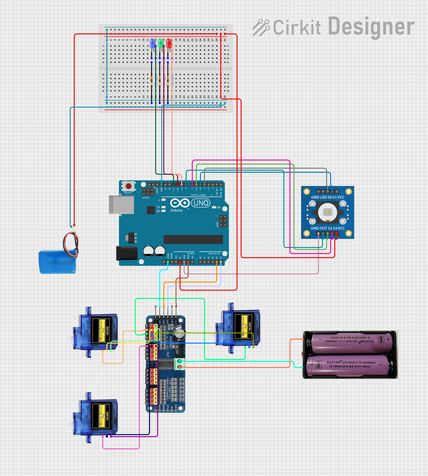
Circuit Documentation
Summary
This circuit is designed to control multiple servos and LEDs using an Arduino UNO microcontroller. It also includes a TCS3200 color sensor for color detection. The servos are controlled via a 16-Channel PWM Servo Driver, and the LEDs are used to indicate the detected color. The circuit is powered by a combination of 7.4V and 5V batteries.
Component List
Arduino UNO
- Description: Microcontroller board based on the ATmega328P.
- Pins: UNUSED, IOREF, Reset, 3.3V, 5V, GND, Vin, A0, A1, A2, A3, A4, A5, SCL, SDA, AREF, D13, D12, D11, D10, D9, D8, D7, D6, D5, D4, D3, D2, D1, D0
16-Channel PWM Servo Driver
- Description: PWM driver for controlling up to 16 servos.
- Pins: V+, VCC, SDA, SCL, OE, GND, Vin+, Vin-, PWM1, PWM2, PWM3, PWM4, PWM5, PWM6, PWM7, PWM8, PWM9, PWM10, PWM11, PWM12, PWM13, PWM14, PWM15, PWM16
Micro servo 9G
- Description: Small servo motor.
- Pins: GND, +5V, PWM
7.4V Battery
- Description: Power source.
- Pins: +, -
5V Battery
- Description: Power source.
- Pins: positive, negative
TCS3200
- Description: Color sensor.
- Pins: GND, OUT, S2, S3, VCC, LED, S0, S1
Resistor (220 Ohms)
- Description: Resistor with 220 Ohms resistance.
- Pins: pin1, pin2
LED: Two Pin (red)
- Description: Red LED.
- Pins: cathode, anode
LED: Two Pin (green)
- Description: Green LED.
- Pins: cathode, anode
LED: Two Pin (blue)
- Description: Blue LED.
- Pins: cathode, anode
Wiring Details
Arduino UNO
- D11: Connected to anode of Blue LED
- D10: Connected to anode of Green LED
- D9: Connected to anode of Red LED
- GND: Connected to pin2 of all resistors and negative of 5V battery
- 5V: Connected to VCC of TCS3200 and positive of 5V battery
- IOREF: Connected to VCC of 16-Channel PWM Servo Driver
- A4: Connected to SDA of 16-Channel PWM Servo Driver
- A5: Connected to SCL of 16-Channel PWM Servo Driver
- D8: Connected to OUT of TCS3200
- D7: Connected to S3 of TCS3200
- D6: Connected to S2 of TCS3200
- D5: Connected to S1 of TCS3200
- D4: Connected to S0 of TCS3200
16-Channel PWM Servo Driver
- V+: Connected to +5V of all Micro servos
- VCC: Connected to IOREF of Arduino UNO
- SDA: Connected to A4 of Arduino UNO
- SCL: Connected to A5 of Arduino UNO
- GND: Connected to GND of Arduino UNO and GND of all Micro servos
- Vin+: Connected to + of 7.4V battery
- Vin-: Connected to - of 7.4V battery
- PWM2: Connected to PWM of Micro servo 9G
- PWM3: Connected to PWM of Micro servo 9G
- PWM5: Connected to PWM of Micro servo 9G
Micro servo 9G
- GND: Connected to GND of 16-Channel PWM Servo Driver
- +5V: Connected to V+ of 16-Channel PWM Servo Driver
- PWM: Connected to PWM2, PWM3, and PWM5 of 16-Channel PWM Servo Driver
7.4V Battery
- +: Connected to Vin+ of 16-Channel PWM Servo Driver
- -: Connected to Vin- of 16-Channel PWM Servo Driver
5V Battery
- positive: Connected to VCC of TCS3200 and 5V of Arduino UNO
- negative: Connected to GND of Arduino UNO and pin2 of all resistors
TCS3200
- GND: Connected to GND of Arduino UNO
- OUT: Connected to D8 of Arduino UNO
- S2: Connected to D6 of Arduino UNO
- S3: Connected to D7 of Arduino UNO
- VCC: Connected to 5V of Arduino UNO
- S0: Connected to D4 of Arduino UNO
- S1: Connected to D5 of Arduino UNO
Resistor (220 Ohms)
- pin1: Connected to cathode of respective LEDs
- pin2: Connected to GND of Arduino UNO and negative of 5V battery
LED: Two Pin (red)
- cathode: Connected to pin1 of Resistor
- anode: Connected to D9 of Arduino UNO
LED: Two Pin (green)
- cathode: Connected to pin1 of Resistor
- anode: Connected to D10 of Arduino UNO
LED: Two Pin (blue)
- cathode: Connected to pin1 of Resistor
- anode: Connected to D11 of Arduino UNO
Code Documentation
#include <Wire.h>
#include <Adafruit_PWMServoDriver.h>

// Create a PWM driver object
Adafruit_PWMServoDriver pwm = Adafruit_PWMServoDriver();

// Servo pulse length values (adjust as needed for specific servo motor)
int minPulse = 150;  // Pulse length for 0 degrees
int maxPulse = 700;  // Pulse length for 180 degrees

// TCS3200 color sensor pins
int S0 = 4; // Frequency scaling pin S0
int S1 = 5; // Frequency scaling pin S1
int S2 = 6; // Color filter pin S2
int S3 = 7; // Color filter pin S3
int OUT = 8; // Output pin for frequency

// LED pins
int redLED = 9;
int greenLED = 10;
int blueLED = 11;

// Helper function to convert degrees to pulse length
int angleToPulse(int angle) {
  return map(angle, 0, 180, minPulse, maxPulse);
}

// Function to rotate the servo to a specific angle
void rotateServo(int channel, int angle) {
  int targetPulse = angleToPulse(angle);
  pwm.setPWM(channel, 0, targetPulse);
}

// Function to initialize TCS3200 sensor
void initColorSensor() {
  pinMode(S0, OUTPUT);
  pinMode(S1, OUTPUT);
  pinMode(S2, OUTPUT);
  pinMode(S3, OUTPUT);
  pinMode(OUT, INPUT);

  // Set frequency scaling
  digitalWrite(S0, HIGH);
  digitalWrite(S1, LOW);
}

// Function to read the frequency of each color
int readColor(int S2_state, int S3_state) {
  digitalWrite(S2, S2_state);
  digitalWrite(S3, S3_state);
  return pulseIn(OUT, digitalRead(OUT) == HIGH ? LOW : HIGH); // Frequency count for the current color
}

void setup() {
  Serial.begin(9600);
  Serial.println("PWM Servo Control with TCS3200 Color Detection");

  pwm.begin();               // Initialize the PWM board
  pwm.setPWMFreq(60);        // Set frequency to 60 Hz (standard for servos)
  delay(10);                 // Short delay for setup

  initColorSensor();         // Initialize TCS3200 sensor

  // Initialize LED pins
  pinMode(redLED, OUTPUT);
  pinMode(greenLED, OUTPUT);
  pinMode(blueLED, OUTPUT);
}

// Function to detect color based on TCS3200 readings
String detectColor() {
  int redFrequency = readColor(LOW, LOW);
  int greenFrequency = readColor(HIGH, HIGH);
  int blueFrequency = readColor(LOW, HIGH);

  Serial.print("Red Frequency: ");
  Serial.println(redFrequency);
  Serial.print("Green Frequency: ");
  Serial.println(greenFrequency);
  Serial.print("Blue Frequency: ");
  Serial.println(blueFrequency);

  // Detect color logic
  if (redFrequency > 200