
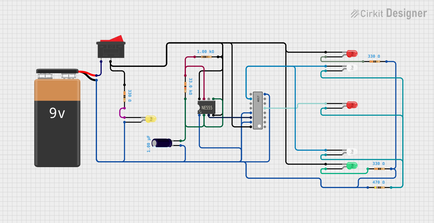
Circuit Documentation
Summary
This circuit appears to be a timer or sequencer circuit utilizing a 555 Timer IC and a 4017 Decade Counter IC to drive multiple LEDs. The 555 Timer IC is likely configured to generate clock pulses that are fed into the 4017 IC, which then sequentially activates its outputs. These outputs are connected to various LEDs through resistors, which may indicate a light sequence or display pattern. A 9V battery powers the circuit, and a rocker switch is used to turn the circuit on and off. An electrolytic capacitor is also present, possibly for power supply decoupling or timing purposes with the 555 Timer IC.
Component List
9V Battery
- Description: Provides the power supply for the circuit.
Electrolytic Capacitor
- Description: Typically used for power supply filtering or timing applications.
- Properties: Capacitance: 1 µF (microfarads)
Resistor
- Description: Used to limit current or divide voltage in the circuit.
- Properties: Various resistances (330 Ω, 33 kΩ, 1 kΩ, 470 Ω)
LED: Two Pin (yellow, white, red, green)
- Description: Light Emitting Diodes of various colors used as visual indicators.
- Properties: Two pins (anode and cathode)
Rocker Switch
- Description: A mechanical switch used to control the power flow in the circuit.
555 Timer IC
- Description: An integrated circuit used for generating precise time delays or oscillations.
4017 Decade Counter IC
- Description: A counter/divider IC that produces a sequence of outputs upon receiving clock pulses.
Wiring Details
9V Battery
- Negative terminal connected to the ground net.
- Positive terminal connected to the rocker switch.
Electrolytic Capacitor
- Negative terminal connected to the ground net.
- Positive terminal connected to the 555 Timer IC's control voltage (CV) and trigger (Trig) pins, and to a 33 kΩ resistor.
Resistor (330 Ω)
- One end connected to the anode of the yellow LED and the other end to the ground net.
- One end connected to the anode of the red LED and the other end to the ground net.
- One end connected to the anode of the green LED and the other end to the ground net.
Resistor (33 kΩ)
- One end connected to the positive terminal of the electrolytic capacitor and the other end to the ground net.
Resistor (1 kΩ)
- One end connected to the discharge (Dis) pin of the 555 Timer IC and the other end to the ground net.
Resistor (470 Ω)
- One end connected to the anode of the red LED and the other end to the ground net.
LED: Two Pin (yellow, white, red, green)
- Cathode connected to the ground net.
- Anode connected to the respective resistor.
Rocker Switch
- One terminal connected to the positive terminal of the 9V battery.
- Other terminal connected to the VCC+ pin of the 555 Timer IC, VCC pin of the 4017 IC, and the anode of the red LED through a 1 kΩ resistor.
555 Timer IC
- Ground (GND) pin connected to the ground net.
- Control voltage (CV) and trigger (Trig) pins connected to the positive terminal of the electrolytic capacitor.
- Discharge (Dis) pin connected to a 1 kΩ resistor.
- Threshold (Th) pin connected to the ground net.
- Reset (Rst) pin connected to the VCC+ pin.
- Output (Out) pin connected to the clock (CLK) input of the 4017 IC.
4017 Decade Counter IC
- Ground (GND) pin connected to the ground net.
- VCC pin connected to the VCC+ pin of the 555 Timer IC.
- Master reset (MR) pin connected to the ground net.
- Clock (CLK) input connected to the output (Out) of the 555 Timer IC.
- Enable (~EN) pin connected to the ground net.
- Outputs (Q0-Q9) connected to various LEDs through resistors.
Documented Code
No code was provided for any microcontrollers in the circuit. If there are microcontrollers present, please provide the code for documentation.