
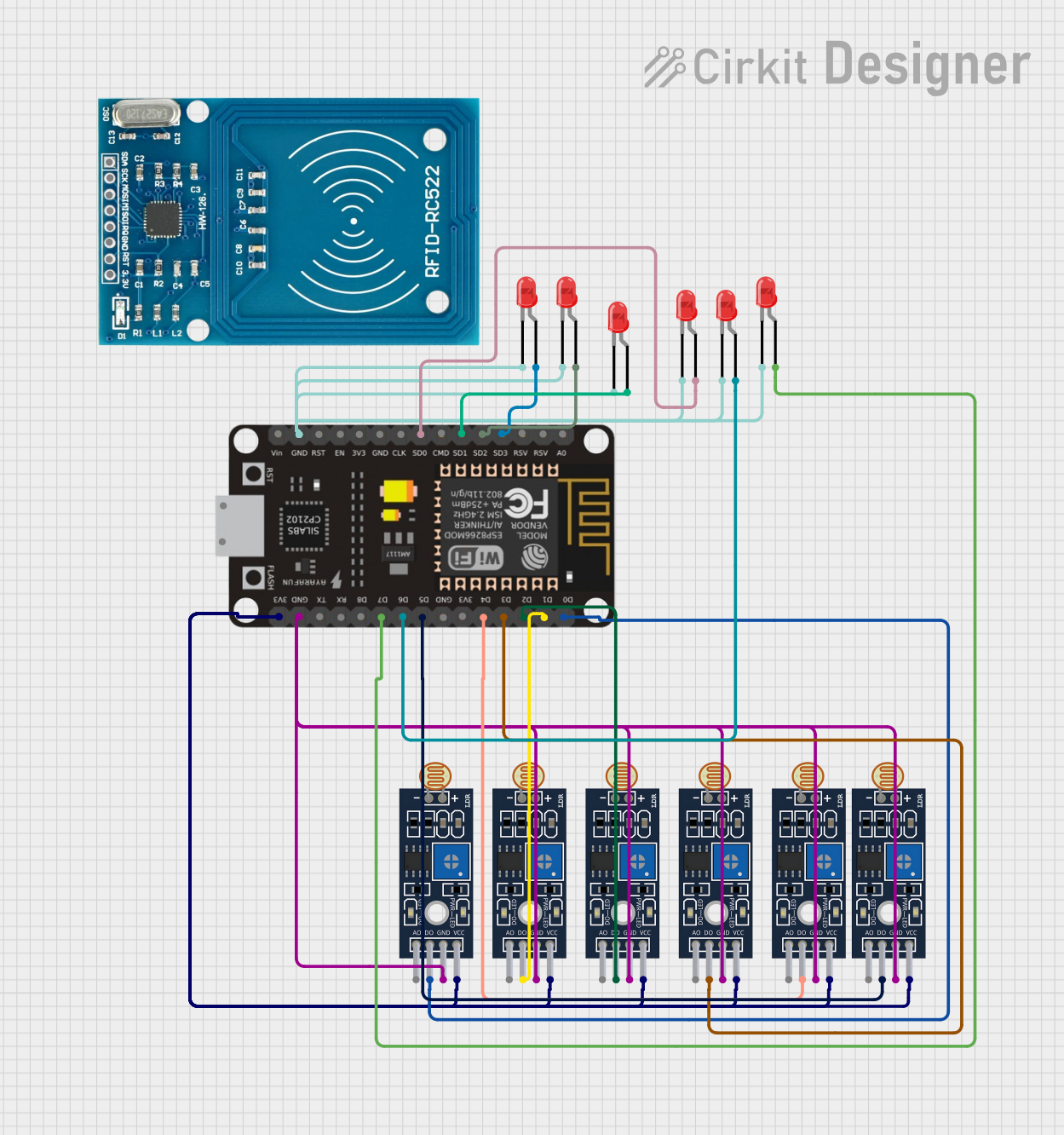
Circuit Documentation
Summary
This circuit is designed around the ESP-8266 microcontroller and includes multiple sensors and indicators. The primary function of the circuit is to monitor light levels using six LDR sensors (LM393) and to provide visual feedback through LED indicators. The ESP-8266 reads the digital outputs from the LDR sensors and, upon detecting a change in light, prints a corresponding number to the console. The LEDs are controlled by the ESP-8266 to indicate various states or events as programmed.
Component List
Microcontroller
- ESP-8266 Controller: A Wi-Fi capable microcontroller with multiple GPIO pins used for interfacing with sensors and LEDs.
Sensors
- Sensor LDR LM393: A light-dependent resistor sensor module with both analog and digital outputs, used to detect the level of light in the environment.
Indicators
- LED: Two Pin (red): A basic red LED used for visual indication.
Communication Modules
- RFID-RC522: An RFID reader/writer module for contactless communication using radio frequency identification.
Wiring Details
ESP-8266 Controller
- Digital Pins (D0-D6): Connected to the digital outputs of the LDR sensors and the anodes of the LEDs.
- 3V3: Powers the LDR sensors.
- GND: Common ground for the LEDs and LDR sensors.
Sensor LDR LM393
- D0: Digital output connected to the corresponding digital pins on the ESP-8266.
- GND: Connected to the ground (GND) of the ESP-8266.
- VCC: Powered by the 3.3V output from the ESP-8266.
LED: Two Pin (red)
- Anode: Connected to various digital pins on the ESP-8266 to be controlled by the microcontroller.
- Cathode: All cathodes are connected together and then to the ground (GND) of the ESP-8266.
RFID-RC522
- VCC (3.3V): Powered by the 3.3V output from the ESP-8266.
- RST, IRQ, MISO, MOSI, SCK, SDA: These pins would typically be connected to the corresponding SPI pins on the ESP-8266, but the connection details are not provided in the net list.
Documented Code
/*
 * This Arduino Sketch is designed for an ESP-8266 microcontroller. It reads the
 * digital output from six LDR sensors (LM393) connected to pins D0 to D5. When
 * any sensor detects a change in light, it prints a corresponding number (1-6)
 * to the console.
 */

void setup() {
  // Initialize serial communication at 115200 baud rate
  Serial.begin(115200);

  // Define pin modes for LDR sensors
  pinMode(D0, INPUT);
  pinMode(D1, INPUT);
  pinMode(D2, INPUT);
  pinMode(D3, INPUT);
  pinMode(D4, INPUT);
  pinMode(D5, INPUT);
}

void loop() {
  // Read the state of each LDR sensor
  if (digitalRead(D0) == HIGH) {
    Serial.println(1);
  }
  if (digitalRead(D1) == HIGH) {
    Serial.println(2);
  }
  if (digitalRead(D2) == HIGH) {
    Serial.println(3);
  }
  if (digitalRead(D3) == HIGH) {
    Serial.println(4);
  }
  if (digitalRead(D4) == HIGH) {
    Serial.println(5);
  }
  if (digitalRead(D5) == HIGH) {
    Serial.println(6);
  }

  // Small delay to avoid flooding the serial console
  delay(100);
}
The code is written for the Arduino platform and is intended to be uploaded to the ESP-8266 microcontroller. It sets up the serial communication and configures the digital pins connected to the LDR sensors as inputs. In the main loop, the code continuously checks the state of each LDR sensor and prints out a number corresponding to the sensor that detects a high signal, indicating a change in light levels. A short delay is included to prevent overwhelming the serial output.