
Arduino Nano-Based Battery-Powered Servo Control with RGB Color Sensing
View and Edit Project In Cirkit Designer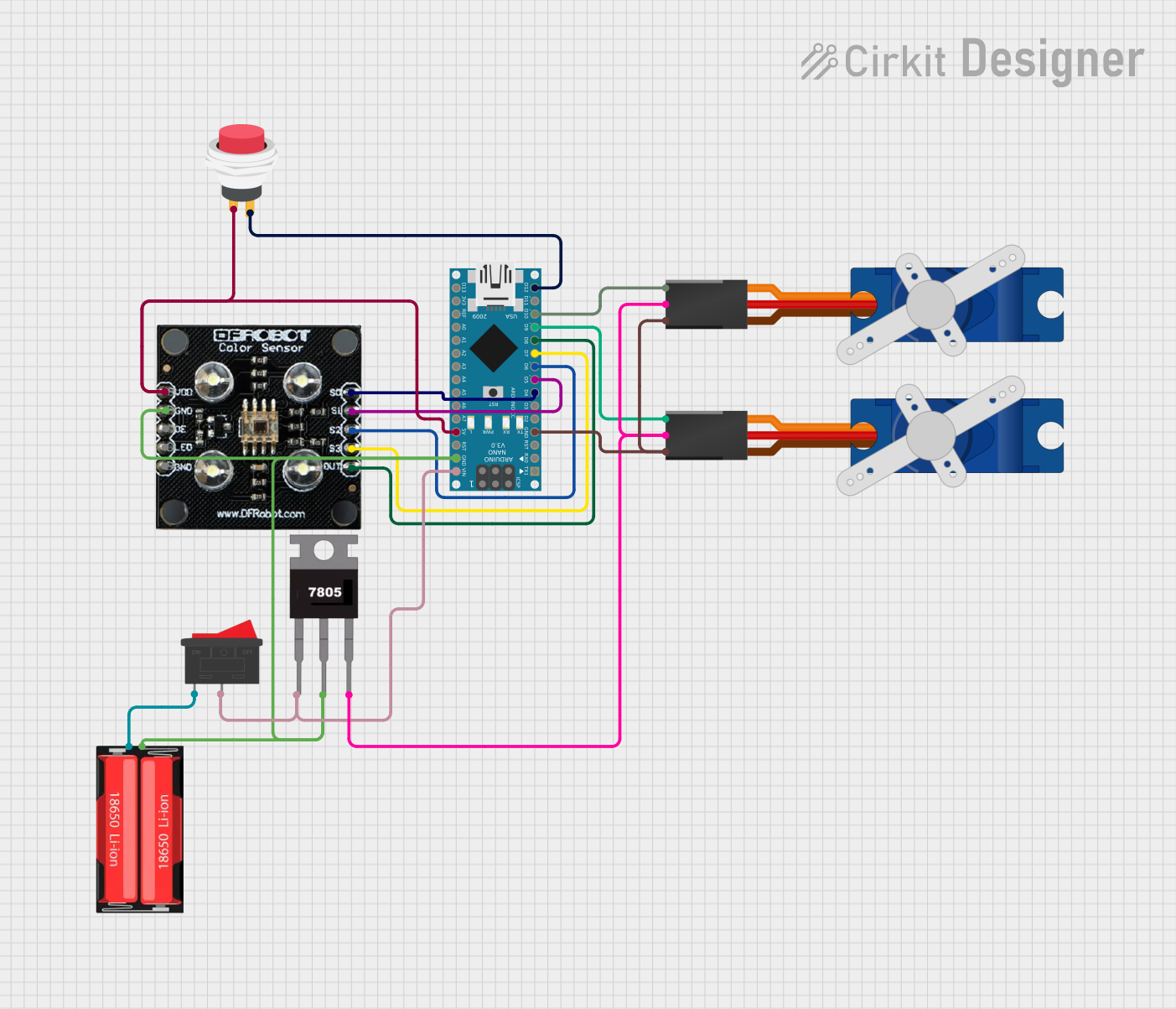
Circuit Documentation
Summary
This circuit involves an Arduino Nano microcontroller, two Tower Pro SG90 servos, an RGB color sensor, a 2-pin push switch, a 7805 voltage regulator, a 18650 Li-Ion battery, and a rocker switch. The Arduino Nano controls the servos and the RGB color sensor, while the power is managed by the 7805 voltage regulator and the 18650 Li-Ion battery.
Component List
Arduino Nano
- Description: A small, complete, and breadboard-friendly board based on the ATmega328P.
- Pins: D1/TX, D0/RX, RESET, GND, D2, D3, D4, D5, D6, D7, D8, D9, D10, D11/MOSI, D12/MISO, VIN, 5V, A7, A6, A5, A4, A3, A2, A1, A0, AREF, 3V3, D13/SCK
Tower Pro SG90 Servo (x2)
- Description: A micro servo motor commonly used in robotics.
- Pins: Signal, +5V, GND
RGB Colour Sensor
- Description: A sensor that detects the color of an object.
- Pins: S0, S1, S2, S3, OUT, Vcc, GND, OE, LED
2-Pin Push Switch
- Description: A simple push-button switch.
- Pins: Input +, Output +
7805 Voltage Regulator
- Description: A voltage regulator that outputs a stable 5V.
- Pins: Vin, Gnd, Vout
18650 Li-Ion Battery
- Description: A rechargeable lithium-ion battery.
- Pins: Positive, Negative
Rocker Switch
- Description: A switch that can be toggled between two positions.
- Pins: 1, 2
Wiring Details
Arduino Nano
- D9: Connected to Signal pin of Tower Pro SG90 servo
- D10: Connected to Signal pin of Tower Pro SG90 servo
- D4: Connected to S0 pin of RGB Colour Sensor
- D5: Connected to S1 pin of RGB Colour Sensor
- D6: Connected to S2 pin of RGB Colour Sensor
- D7: Connected to S3 pin of RGB Colour Sensor
- D8: Connected to OUT pin of RGB Colour Sensor
- D12/MISO: Connected to Output + pin of 2-Pin Push Switch
- VIN: Connected to pin 2 of Rocker Switch and Vin pin of 7805 Voltage Regulator
- GND: Connected to GND pin of Tower Pro SG90 servo, GND pin of RGB Colour Sensor, Negative pin of 18650 Li-Ion Battery, and Gnd pin of 7805 Voltage Regulator
- 5V: Connected to Vcc pin of RGB Colour Sensor and Input + pin of 2-Pin Push Switch
Tower Pro SG90 Servo (1)
- Signal: Connected to D9 pin of Arduino Nano
- +5V: Connected to Vout pin of 7805 Voltage Regulator
- GND: Connected to GND pin of Arduino Nano
Tower Pro SG90 Servo (2)
- Signal: Connected to D10 pin of Arduino Nano
- +5V: Connected to Vout pin of 7805 Voltage Regulator
- GND: Connected to GND pin of Arduino Nano
RGB Colour Sensor
- S0: Connected to D4 pin of Arduino Nano
- S1: Connected to D5 pin of Arduino Nano
- S2: Connected to D6 pin of Arduino Nano
- S3: Connected to D7 pin of Arduino Nano
- OUT: Connected to D8 pin of Arduino Nano
- Vcc: Connected to 5V pin of Arduino Nano
- GND: Connected to GND pin of Arduino Nano
2-Pin Push Switch
- Input +: Connected to 5V pin of Arduino Nano
- Output +: Connected to D12/MISO pin of Arduino Nano
7805 Voltage Regulator
- Vin: Connected to VIN pin of Arduino Nano and pin 2 of Rocker Switch
- Gnd: Connected to GND pin of Arduino Nano and Negative pin of 18650 Li-Ion Battery
- Vout: Connected to +5V pin of Tower Pro SG90 servos
18650 Li-Ion Battery
- Positive: Connected to pin 1 of Rocker Switch
- Negative: Connected to GND pin of Arduino Nano and Gnd pin of 7805 Voltage Regulator
Rocker Switch
- 1: Connected to Positive pin of 18650 Li-Ion Battery
- 2: Connected to VIN pin of Arduino Nano and Vin pin of 7805 Voltage Regulator
Documented Code
Arduino Nano Code (sketch.ino)
void setup() {
  // put your setup code here, to run once:

}

void loop() {
  // put your main code here, to run repeatedly:

}
Additional Documentation (documentation.txt)
This documentation provides a comprehensive overview of the circuit, including a summary, detailed component list, wiring details, and the code used in the Arduino Nano.