ESP32-Based Autonomous Robot with Obstacle Avoidance

Circuit Documentation
Summary
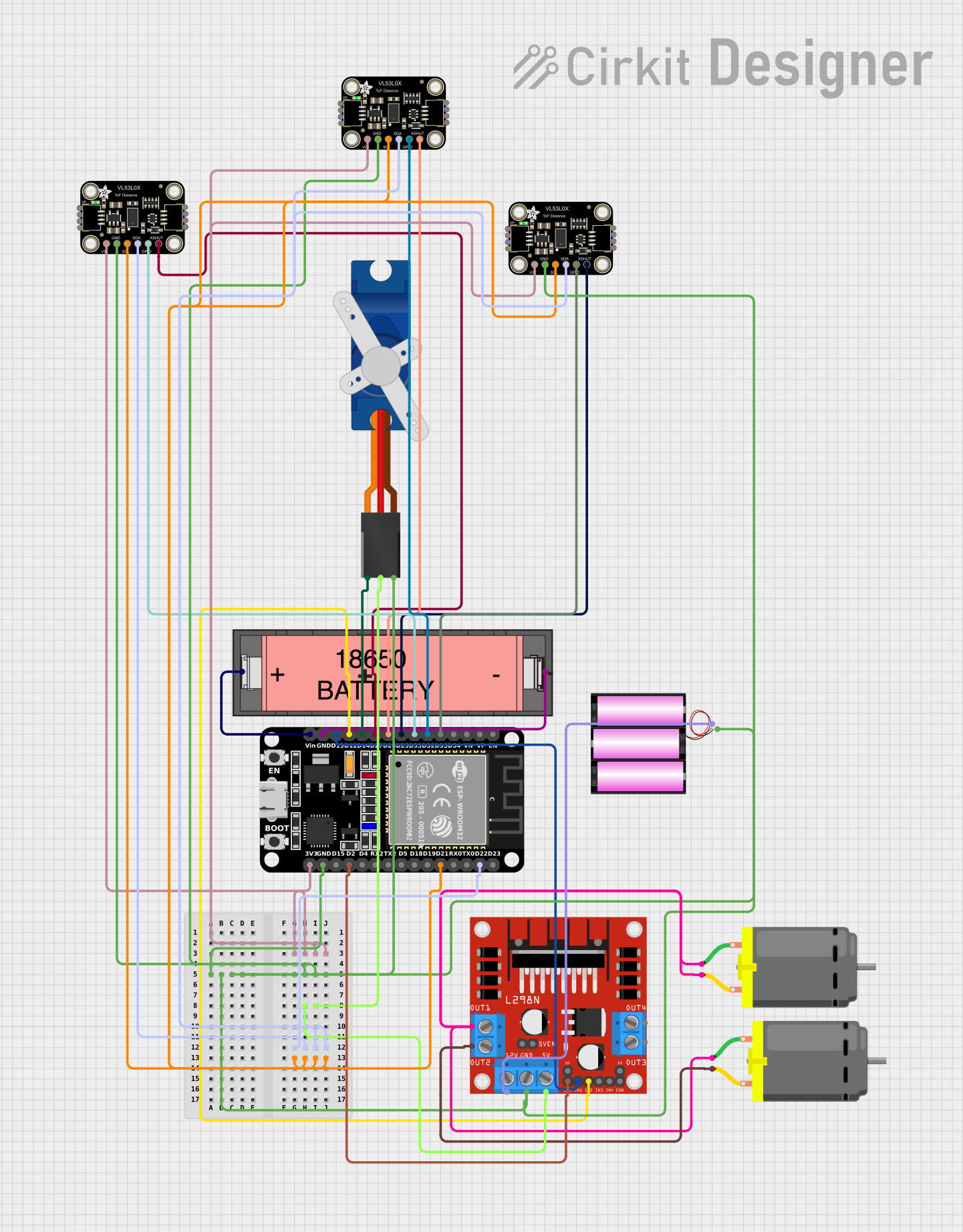
This circuit integrates various components to perform a set of functions that likely involve motion control and distance sensing. The main controller is an ESP32 microcontroller, which interfaces with a DC motor driver, servo motor, and multiple time-of-flight distance sensors. The ESP32 is powered by a Li-ion 18650 battery, and the DC motor driver is powered by a separate 12V battery. The DC motor driver controls two DC motors, and the servo motor is controlled directly by the ESP32. The distance sensors are used to measure distances and are connected to the ESP32 via I2C communication protocol.
Component List
ESP32 (30 pin)
- Microcontroller with WiFi and Bluetooth capabilities.
- It has a variety of digital I/O pins and supports serial communication protocols like I2C and UART.
L298N DC Motor Driver
- A module capable of driving two DC motors with direction and speed control.
- It has an onboard 5V regulator which can be used to power other components.
Tower Pro SG90 Servo
- A small and lightweight servo motor used for precise angular movement.
DC Motor
- A standard DC motor used for rotational motion.
Li-ion 18650 Battery
- A rechargeable battery that provides power to the ESP32.
Adafruit VL53L0X Time of Flight Distance Sensor
- A sensor that measures distances using time-of-flight technology.
- Multiple sensors are used in the circuit, likely for sensing at different points.
Battery 12V
- A 12V battery used to power the L298N DC motor driver.
Wiring Details
ESP32 (30 pin)
3V3connected to VCC of all Adafruit VL53L0X sensors.GNDconnected to GND of all components.D22(SDA) andD21(SCL) connected to SDA and SCL of all Adafruit VL53L0X sensors for I2C communication.D35,D32,D33connected to GPIO pins of Adafruit VL53L0X sensors for additional functionality or control.D25,D26,D27connected to XSHUT pins of Adafruit VL53L0X sensors to enable/disable them.D14connected to the Signal pin of the Tower Pro SG90 servo.D12,D13connected to IN2 and IN1 of the L298N DC motor driver for motor direction control.Vinconnected to the "+" of the Li-ion 18650 Battery for power.D2connected to ENA of the L298N DC motor driver for motor speed control.
L298N DC Motor Driver
OUT1,OUT2connected to pin 1 of both DC Motors.12Vconnected to the "+" of the 12V battery.5Vconnected to the +5V of the Tower Pro SG90 servo.GNDconnected to the "-" of the 12V battery and GND of the Tower Pro SG90 servo.
Tower Pro SG90 Servo
Signalconnected to D14 of the ESP32.+5Vconnected to 5V of the L298N DC motor driver.GNDconnected to GND of the L298N DC motor driver.
DC Motors
pin 1of each motor connected to OUT1 and OUT2 of the L298N DC motor driver.pin 2of each motor connected to OUT2 and OUT1 of the L298N DC motor driver (respectively, for reverse polarity).
Li-ion 18650 Battery
+connected to Vin of the ESP32.-connected to GND of the ESP32.
Adafruit VL53L0X Time of Flight Distance Sensors
VCCconnected to 3V3 of the ESP32.GNDconnected to GND of the ESP32.SCLconnected to D21 (SCL) of the ESP32.SDAconnected to D22 (SDA) of the ESP32.GPIOconnected to D35, D32, D33 of the ESP32 (specific to each sensor).XSHUTconnected to D25, D26, D27 of the ESP32 (specific to each sensor).
Battery 12V
+connected to 12V of the L298N DC motor driver.-connected to GND of the L298N DC motor driver.
Documented Code
No code was provided for the microcontrollers in the circuit. The documentation of the code would typically include descriptions of the functions, initialization of peripherals, and the main control loop, along with any interrupt service routines or helper functions. Since no code is available, this section cannot be completed. If code becomes available, it should be documented here with comments explaining the purpose and functionality of each section of the code.