Cirkit Designer
Your all-in-one circuit design IDE
Home /
Project Documentation
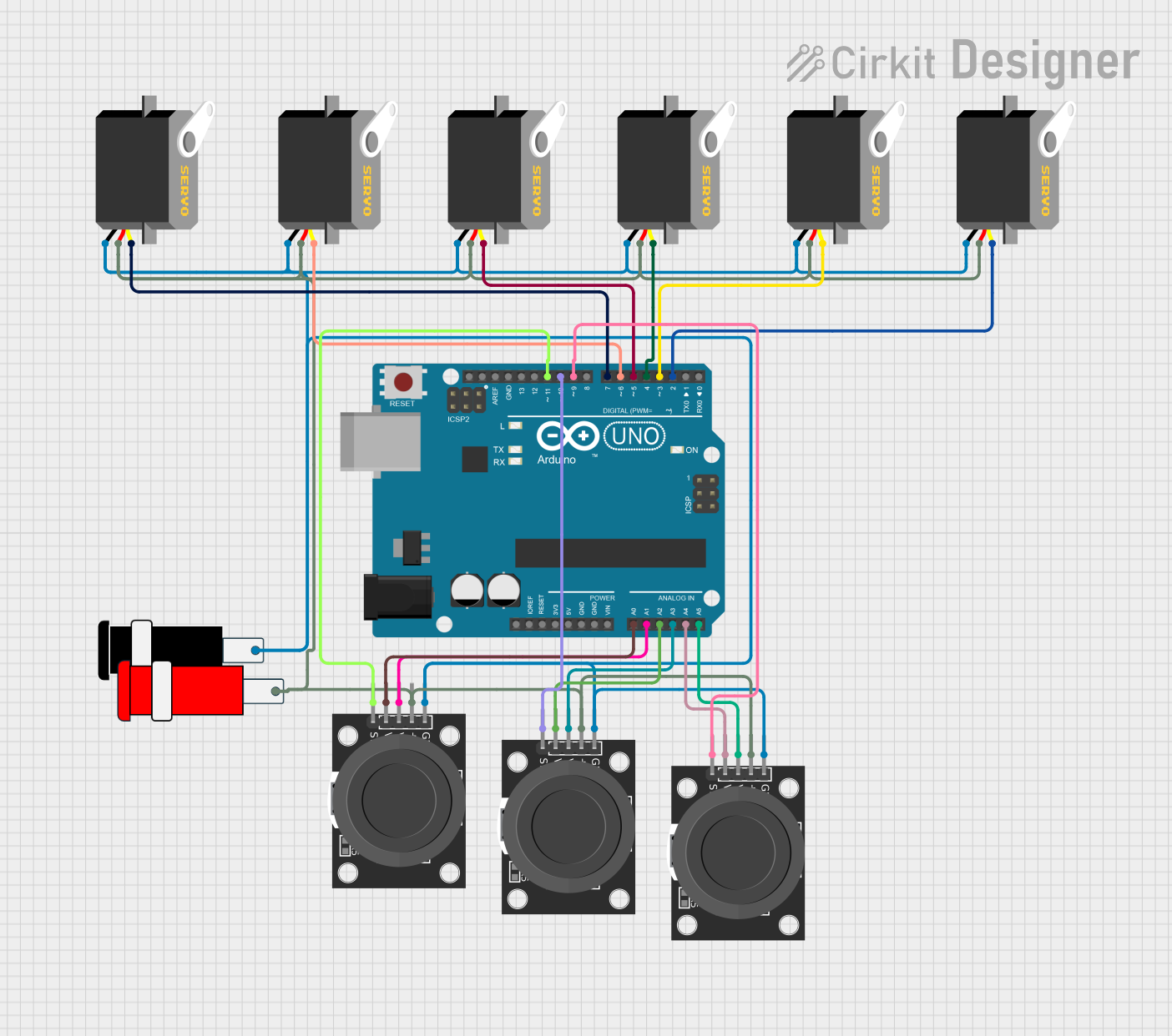
Arduino UNO-Based Multi-Servo Robotic Arm Controlled by Joysticks
Circuit Documentation
Summary
This circuit involves an Arduino UNO microcontroller interfacing with multiple servos and joystick modules. The Arduino UNO reads analog signals from the joysticks and controls the servos based on these inputs. Additionally, the circuit includes a 5V power connector to supply power to the components.
Component List
Arduino UNO
- Description: A microcontroller board based on the ATmega328P.
- Pins: UNUSED, IOREF, Reset, 3.3V, 5V, GND, Vin, A0, A1, A2, A3, A4, A5, SCL, SDA, AREF, D13, D12, D11, D10, D9, D8, D7, D6, D5, D4, D3, D2, D1, D0
Servo (x7)
- Description: A servo motor used for precise control of angular position.
- Pins: gnd, vcc, pulse
KY-023 Dual Axis Joystick Module (x3)
- Description: A joystick module that provides analog output for X and Y axes and a digital output for the switch.
- Pins: GND, +5V, VRx, VRy, SW
Connector 5V
- Description: A connector to supply 5V power to the circuit.
- Pins: GND, VCC
Wiring Details
Arduino UNO
- A0: Connected to VRy of Joystick 1
- A1: Connected to VRx of Joystick 1
- A2: Connected to VRy of Joystick 2
- A3: Connected to VRx of Joystick 2
- A4: Connected to VRy of Joystick 3
- A5: Connected to VRx of Joystick 3
- D11: Connected to SW of Joystick 1
- D10: Connected to SW of Joystick 2
- D9: Connected to SW of Joystick 3
- D7: Connected to pulse of Servo 1
- D6: Connected to pulse of Servo 2
- D5: Connected to pulse of Servo 3
- D4: Connected to pulse of Servo 4
- D3: Connected to pulse of Servo 5
- D2: Connected to pulse of Servo 6
Servo 1
- gnd: Connected to GND of Joystick 1
- vcc: Connected to +5V of Joystick 1
- pulse: Connected to D7 of Arduino UNO
Servo 2
- gnd: Connected to GND of Joystick 1
- vcc: Connected to +5V of Joystick 1
- pulse: Connected to D6 of Arduino UNO
Servo 3
- gnd: Connected to GND of Joystick 1
- vcc: Connected to +5V of Joystick 1
- pulse: Connected to D5 of Arduino UNO
Servo 4
- gnd: Connected to GND of Joystick 1
- vcc: Connected to +5V of Joystick 1
- pulse: Connected to D4 of Arduino UNO
Servo 5
- gnd: Connected to GND of Joystick 1
- vcc: Connected to +5V of Joystick 1
- pulse: Connected to D3 of Arduino UNO
Servo 6
- gnd: Connected to GND of Joystick 1
- vcc: Connected to +5V of Joystick 1
- pulse: Connected to D2 of Arduino UNO
Joystick 1
- GND: Connected to GND of Connector 5V
- +5V: Connected to VCC of Connector 5V
- VRx: Connected to A1 of Arduino UNO
- VRy: Connected to A0 of Arduino UNO
- SW: Connected to D11 of Arduino UNO
Joystick 2
- GND: Connected to GND of Connector 5V
- +5V: Connected to VCC of Connector 5V
- VRx: Connected to A3 of Arduino UNO
- VRy: Connected to A2 of Arduino UNO
- SW: Connected to D10 of Arduino UNO
Joystick 3
- GND: Connected to GND of Connector 5V
- +5V: Connected to VCC of Connector 5V
- VRx: Connected to A5 of Arduino UNO
- VRy: Connected to A4 of Arduino UNO
- SW: Connected to D9 of Arduino UNO
Connector 5V
- GND: Connected to GND of all Joysticks and Servos
- VCC: Connected to +5V of all Joysticks and Servos
Code Documentation
#include <Servo.h>

// Declaration of servo objects
Servo servo_0, servo_1, servo_2, servo_3, servo_4, servo_5, servo_6;

// Joystick analog pins
const int joystick1_x = A0, joystick1_y = A1;
const int joystick2_x = A2, joystick2_y = A3;
const int joystick3_x = A4, joystick3_y = A5;

// Switch pins
const int switchPin1 = 9; // Switch for joystick 1
const int switchPin2 = 10; // Switch for joystick 2
const int switchPin3 = 11; // Switch for joystick 3

void setup() {
  Serial.begin(9600); // Initialize serial communication

  // Initialize switch pins as input with internal pull-up resistors
  pinMode(switchPin1, INPUT_PULLUP);
  pinMode(switchPin2, INPUT_PULLUP);
  pinMode(switchPin3, INPUT_PULLUP);

  // Attach servos to pins
  servo_0.attach(2);
  servo_1.attach(3);
  servo_2.attach(4);
  servo_3.attach(5);
  servo_4.attach(6);
  servo_5.attach(7);
  servo_6.attach(8);
}

void loop() {
  // Handle joystick control
  handleJoystickControl();

  // Handle serial input
  if (Serial.available() > 0) {
    handleSerialInput();
  }

  // Small delay to avoid overwhelming the servos
  delay(20);
}

void handleJoystickControl() {
  // Read the switch states
  bool switchState1 = digitalRead(switchPin1) == LOW;
  bool switchState2 = digitalRead(switchPin2) == LOW;
  bool switchState3 = digitalRead(switchPin3) == LOW;

  if (switchState1) {
    // Read joystick 1 values and control servo_0 and servo_1
    int servo_0_pos = map(analogRead(joystick1_x), 0, 1023, 0, 180);
    int servo_1_pos = map(analogRead(joystick1_y), 0, 1023, 0, 180);
    servo_0.write(servo_0_pos);
    servo_1.write(servo_1_pos);
  }

  if (switchState2) {
    // Read joystick 2 values and control servo_2 and servo_3
    int servo_2_pos = map(analogRead(joystick2_x), 0, 1023, 0, 180);
    int servo_3_pos = map(analogRead(joystick2_y), 0, 1023, 0, 180);
    servo_2.write(servo_2_pos);
    servo_3.write(servo_3_pos);
  }

  if (switchState3) {
    // Read joystick 3 values and control servo_4, servo_5, and servo_6
    int servo_4_pos = map(analogRead(joystick3_x), 0, 1023, 0, 180);
    int servo_5_pos = map(analogRead(joystick3_y), 0, 1023, 0, 180);
    int servo_6_pos = 180 - servo_4_pos; // Synchronize servo_6 with servo_4
    servo_4.write(servo_4_pos);
    servo_5.write(servo_5_pos);
    servo_6.write(servo_6_pos);
  }
}

void handleSerialInput() {
  // Read the data string from the serial input
  String input = Serial.readStringUntil('\n');
  int servoIndex = input.substring(0, 1).toInt(); // Get the servo index
  int servoValue = input.substring(2).toInt(); // Get the servo value

  // Write the value to the corresponding servo
  switch (servoIndex) {
    case 1:
      servo_0