Cirkit Designer
Your all-in-one circuit design IDE
Home /
Project Documentation
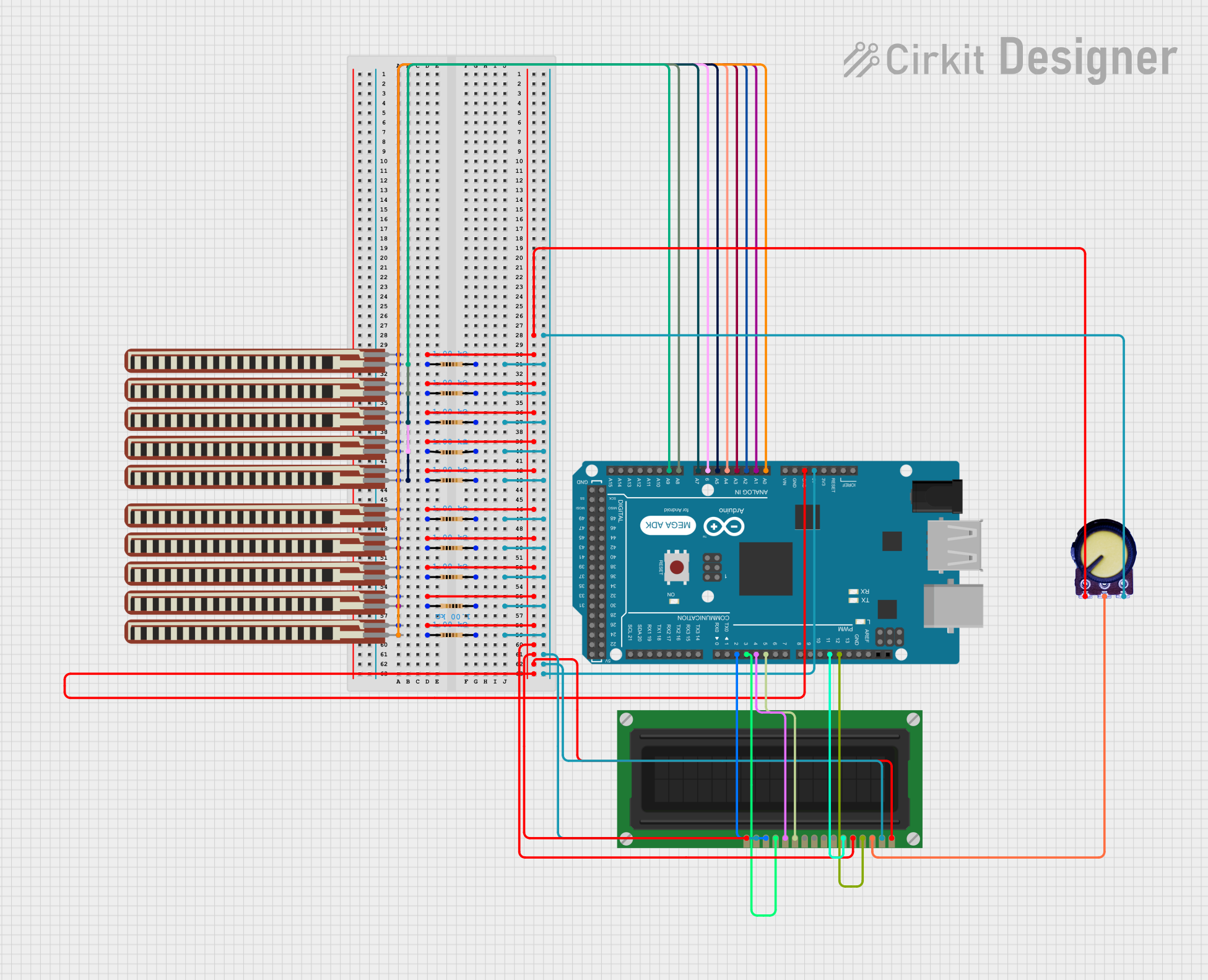
Arduino Mega ADK Flex Sensor-Controlled LCD Display
Circuit Documentation
Summary
This document provides a detailed overview of a circuit that includes an LCD Display, multiple resistors, flex resistors, a potentiometer, and an Arduino Mega ADK (Rev3). The circuit is designed to interface the LCD Display with the Arduino Mega ADK, using various resistors and a potentiometer to control and manage the signals.
Component List
LCD Display (16 pin)
- Description: A 16-pin LCD display used for visual output.
- Pins: VSS, VDD, VO, RS, R_W, E, DB0, DB1, DB2, DB3, DB4, DB5, DB6, DB7, A, K
2.2 inch Basic Flex Resistor
- Description: A basic flex resistor used for sensing flex or bend.
- Pins: Pin 2, pin 1
Resistor
- Description: A standard resistor with a resistance of 1000 Ohms.
- Pins: pin1, pin2
- Properties: Resistance: 1000 Ohms
Potentiometer
- Description: A variable resistor used to adjust voltage levels.
- Pins: GND, Output, VCC
Arduino Mega ADK (Rev3)
- Description: A microcontroller board based on the ATmega2560.
- Pins: A comprehensive list of analog and digital pins including A0-A15, D0-D53, PWM pins, and power pins.
Wiring Details
LCD Display (16 pin)
- VSS: Connected to GND (Arduino Mega ADK)
- VDD: Connected to 5V (Arduino Mega ADK)
- VO: Connected to Output (Potentiometer)
- RS: Connected to D12 PWM (Arduino Mega ADK)
- R_W: Connected to GND (Common Ground)
- E: Connected to D11 PWM (Arduino Mega ADK)
- DB4: Connected to D5 PWM (Arduino Mega ADK)
- DB5: Connected to D4 PWM (Arduino Mega ADK)
- DB6: Connected to D3 PWM (Arduino Mega ADK)
- DB7: Connected to D2 PWM (Arduino Mega ADK)
- A: Connected to 5V (Arduino Mega ADK)
- K: Connected to GND (Common Ground)
2.2 inch Basic Flex Resistor
- Pin 1: Connected to GND (Common Ground)
- Pin 2: Connected to:
- pin1 (Resistor)
- A0 (Arduino Mega ADK)
- A1 (Arduino Mega ADK)
- A2 (Arduino Mega ADK)
- A3 (Arduino Mega ADK)
- A4 (Arduino Mega ADK)
- A5 (Arduino Mega ADK)
- A6 (Arduino Mega ADK)
- A7 (Arduino Mega ADK)
- A8 (Arduino Mega ADK)
- A9 (Arduino Mega ADK)
Resistor
- pin1: Connected to:
- Pin 2 (2.2 inch Basic Flex Resistor)
- A0 (Arduino Mega ADK)
- A1 (Arduino Mega ADK)
- A2 (Arduino Mega ADK)
- A3 (Arduino Mega ADK)
- A4 (Arduino Mega ADK)
- A5 (Arduino Mega ADK)
- A6 (Arduino Mega ADK)
- A7 (Arduino Mega ADK)
- A8 (Arduino Mega ADK)
- A9 (Arduino Mega ADK)
- pin2: Connected to:
- pin2 (Other Resistors)
- VCC (Potentiometer)
- A (LCD Display)
- 5V (Arduino Mega ADK)
Potentiometer
- GND: Connected to GND (Common Ground)
- Output: Connected to VO (LCD Display)
- VCC: Connected to pin2 (Resistor)
Arduino Mega ADK (Rev3)
- GND: Connected to GND (Common Ground)
- 5V: Connected to VDD (LCD Display) and A (LCD Display)
- A0: Connected to pin1 (Resistor)
- A1: Connected to pin1 (Resistor)
- A2: Connected to pin1 (Resistor)
- A3: Connected to pin1 (Resistor)
- A4: Connected to pin1 (Resistor)
- A5: Connected to pin1 (Resistor)
- A6: Connected to pin1 (Resistor)
- A7: Connected to pin1 (Resistor)
- A8: Connected to pin1 (Resistor)
- A9: Connected to pin1 (Resistor)
- D2 PWM: Connected to DB7 (LCD Display)
- D3 PWM: Connected to DB6 (LCD Display)
- D4 PWM: Connected to DB5 (LCD Display)
- D5 PWM: Connected to DB4 (LCD Display)
- D11 PWM: Connected to E (LCD Display)
- D12 PWM: Connected to RS (LCD Display)
Code
No code is provided for this circuit.
This document provides a comprehensive overview of the circuit, including a summary, component list, wiring details, and code section. Each component is described, and its connections are detailed to ensure clarity and ease of understanding.