
Arduino UNO-Based Heart Rate Monitor with GSM Reporting and Motor Control
View and Edit Project In Cirkit Designer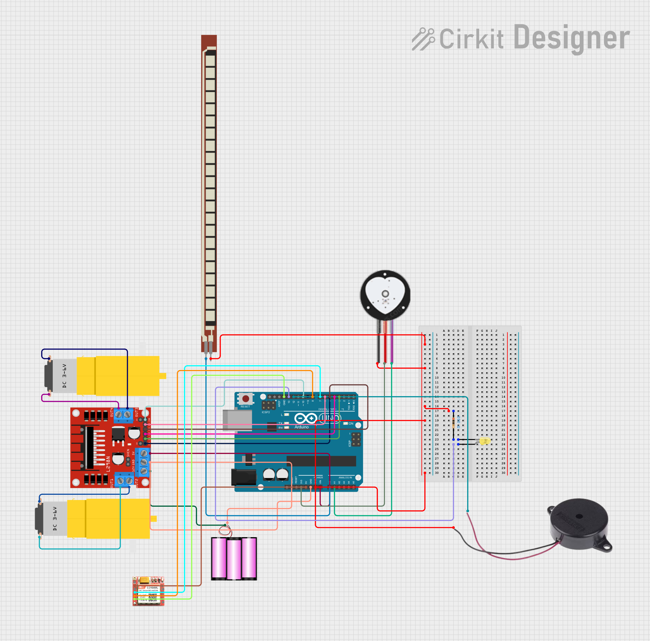
Circuit Documentation
Summary
This circuit integrates various components controlled by an Arduino UNO microcontroller to perform a range of functions. It includes a heart pulse sensor for biometric sensing, a buzzer for audio signaling, an L298N DC motor driver to control two hobby motors, a SIM800L module for cellular communication, and a 12V battery as the power source. The circuit also features a basic flex resistor and a yellow LED with a resistor for visual indication. The Arduino UNO manages the inputs and outputs, interfacing with the sensors, the motor driver, the communication module, and the LED.
Component List
Arduino UNO
A microcontroller board based on the ATmega328P. It has digital input/output pins, analog inputs, a USB connection for programming, and power management features.
Buzzer
An electromechanical component that produces sound when an electrical signal is applied.
Heart Pulse Sensor
A sensor used to detect the heartbeat rate of an individual.
L298N DC Motor Driver
A module capable of driving two DC motors or one stepper motor with current control and thermal protection.
Motor Amarillo Motorreductor Hobby (x2)
Hobbyist DC motors with gear reduction for increased torque.
SIM800L
A GSM/GPRS module that allows cellular network communication for voice calls, SMS, and data.
Battery 12V
A 12-volt battery that provides power to the circuit.
LED: Two Pin (Yellow)
A yellow light-emitting diode used as a visual indicator.
Resistor (200 Ohms)
A passive two-terminal electrical component that implements electrical resistance as a circuit element.
Basic Flex Resistor
A variable resistor that changes its resistance when bent.
Wiring Details
Arduino UNO
- GND connected to:
- Heart Pulse Sensor (GND)
- Buzzer (NEGATIVE)
- Basic Flex Resistor (Pin 2)
- Resistor (pin1)
- L298N DC Motor Driver (GND)
- SIM800L (GND)
- 3.3V connected to Heart Pulse Sensor (VCC)
- 5V connected to SIM800L (VCC)
- Vin connected to L298N DC Motor Driver (5V)
- A0 connected to Basic Flex Resistor (Pin 1)
- A1 connected to Heart Pulse Sensor (SIGNAL)
- D3 connected to L298N DC Motor Driver (IN1)
- D4 connected to L298N DC Motor Driver (IN2)
- D5 connected to L298N DC Motor Driver (IN3)
- D6 connected to L298N DC Motor Driver (IN4)
- D7 connected to SIM800L (RXD)
- D8 connected to SIM800L (TXD)
- D9 connected to L298N DC Motor Driver (ENA)
- D10 connected to L298N DC Motor Driver (ENB)
- D12 connected to Buzzer (POSITIVE)
- D13 connected to LED (anode)
Buzzer
- NEGATIVE connected to Arduino UNO (GND)
- POSITIVE connected to Arduino UNO (D12)
Heart Pulse Sensor
- GND connected to Arduino UNO (GND)
- VCC connected to Arduino UNO (3.3V)
- SIGNAL connected to Arduino UNO (A1)
L298N DC Motor Driver
- GND connected to Battery 12V (-) and Arduino UNO (GND)
- 5V connected to Arduino UNO (Vin)
- 12V connected to Battery 12V (+)
- ENA connected to Arduino UNO (D9)
- ENB connected to Arduino UNO (D10)
- IN1 connected to Arduino UNO (D3)
- IN2 connected to Arduino UNO (D4)
- IN3 connected to Arduino UNO (D5)
- IN4 connected to Arduino UNO (D6)
- OUT1 connected to Motor Amarillo Motorreductor Hobby (GND)
- OUT2 connected to Motor Amarillo Motorreductor Hobby (vcc)
- OUT3 connected to Motor Amarillo Motorreductor Hobby (vcc)
- OUT4 connected to Motor Amarillo Motorreductor Hobby (GND)
Motor Amarillo Motorreductor Hobby
- GND connected to L298N DC Motor Driver (OUT1)
- vcc connected to L298N DC Motor Driver (OUT2)
SIM800L
- GND connected to Arduino UNO (GND)
- VCC connected to Arduino UNO (5V)
- RXD connected to Arduino UNO (D7)
- TXD connected to Arduino UNO (D8)
Battery 12V
- (+) connected to L298N DC Motor Driver (12V)
- (-) connected to L298N DC Motor Driver (GND)
LED: Two Pin (Yellow)
- anode connected to Arduino UNO (D13)
- cathode connected to Resistor (pin2)
Resistor (200 Ohms)
- pin1 connected to Basic Flex Resistor (Pin 2)
- pin2 connected to LED (cathode)
Basic Flex Resistor
- Pin 1 connected to Arduino UNO (A0)
- Pin 2 connected to Resistor (pin1)
Documented Code
Arduino UNO Code (sketch.ino)
void setup() {
  // put your setup code here, to run once:

}

void loop() {
  // put your main code here, to run repeatedly:

}
Note: The provided code is a template and does not include any functional code. It needs to be populated with the logic to control the components based on the circuit's requirements.