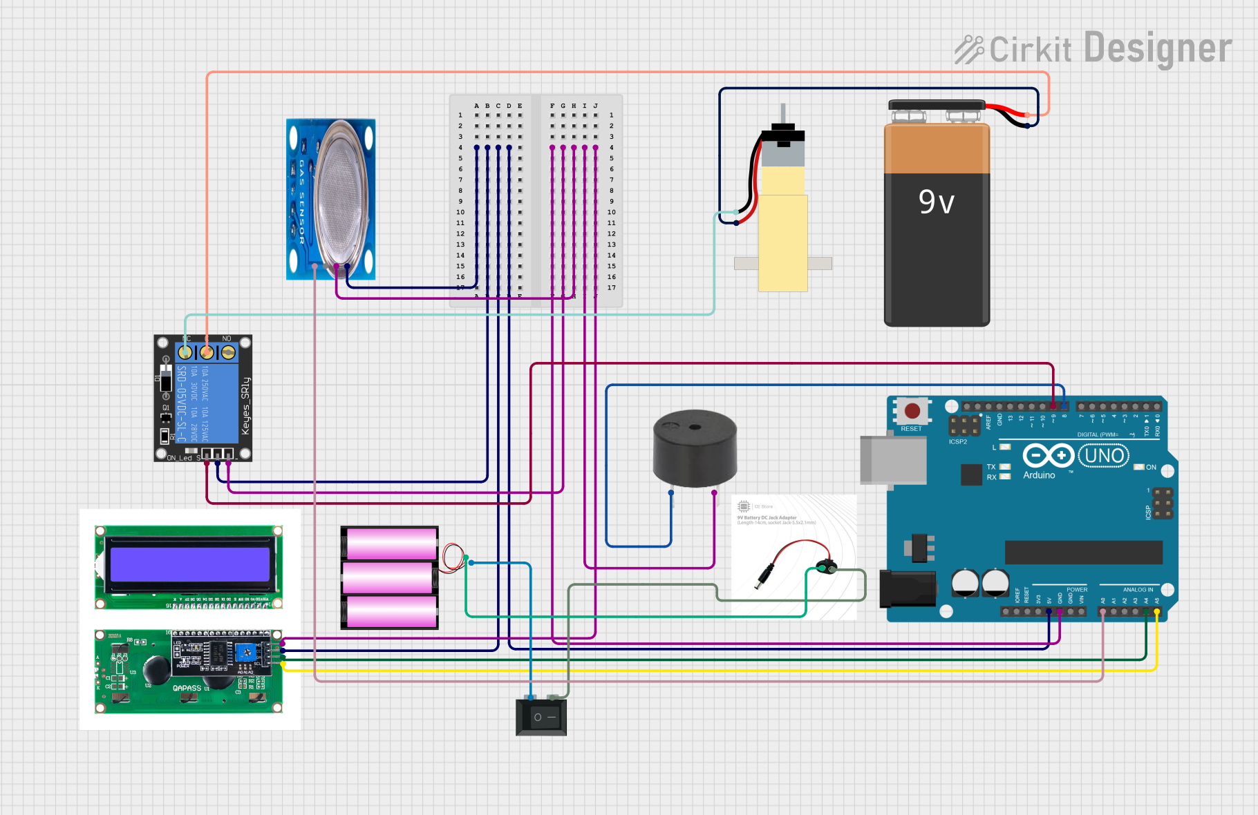
Arduino UNO Gas Leak Detection System with LCD Display and Buzzer Alert

Circuit Documentation
Summary
This document provides a detailed overview of a circuit that includes an Arduino UNO microcontroller, various sensors, actuators, and power components. The circuit is designed to interface with an MQ-5 gas sensor, a 1-channel relay, a buzzer, a hobby gear motor, an LCD display with I2C interface, and power components including a 9V battery and a 12V battery. The Arduino UNO serves as the central control unit, managing inputs from sensors and controlling outputs to actuators.
Component List
MQ-5 Gas Sensor
- Description: Gas sensor for detecting LPG, natural gas, and coal gas.
- Pins: VCC, GND, Digi Out, Analog out
1-Channel Relay (5V 10A)
- Description: Relay module for switching high-power devices.
- Pins: NC, signal, C, power, NO, ground
Buzzer
- Description: Simple buzzer for audio alerts.
- Pins: PIN, GND
Hobby Gearmotor with 48:1 Gearbox
- Description: DC motor with a 48:1 gearbox for mechanical movement.
- Pins: pin 1, pin 2
Arduino UNO
- Description: Microcontroller board based on the ATmega328P.
- Pins: UNUSED, IOREF, Reset, 3.3V, 5V, GND, Vin, A0, A1, A2, A3, A4, A5, SCL, SDA, AREF, D13, D12, D11, D10, D9, D8, D7, D6, D5, D4, D3, D2, D1, D0
LCD with I2C Interface
- Description: LCD display with I2C interface for easy communication.
- Pins: GND, VCC, SDA, SCL
Rocker Switch (SPST)
- Description: Single-pole single-throw switch for power control.
- Pins: 1, 2
12V Battery
- Description: Power source for the circuit.
- Pins: +, -
9V Battery
- Description: Additional power source for the circuit.
- Pins: -, +
Power Jack
- Description: Connector for external power supply.
- Pins: vcc, gnd
Wiring Details
MQ-5 Gas Sensor
- VCC: Connected to Arduino UNO 5V
- GND: Connected to Arduino UNO GND
- Analog out: Connected to Arduino UNO A0
1-Channel Relay (5V 10A)
- power: Connected to Arduino UNO 5V
- ground: Connected to Arduino UNO GND
- signal: Connected to Arduino UNO D9
- NC: Connected to Hobby Gearmotor pin 1
- C: Connected to 9V Battery +
- NO: Not connected
Buzzer
- PIN: Connected to Arduino UNO D8
- GND: Connected to Arduino UNO GND
Hobby Gearmotor with 48:1 Gearbox
- pin 1: Connected to 1-Channel Relay NC
- pin 2: Connected to 9V Battery -
Arduino UNO
- 5V: Connected to MQ-5 VCC, LCD VCC, 1-Channel Relay power
- GND: Connected to Buzzer GND, MQ-5 GND, LCD GND, 1-Channel Relay ground
- A0: Connected to MQ-5 Analog out
- D9: Connected to 1-Channel Relay signal
- D8: Connected to Buzzer PIN
- A4: Connected to LCD SDA
- A5: Connected to LCD SCL
LCD with I2C Interface
- VCC: Connected to Arduino UNO 5V
- GND: Connected to Arduino UNO GND
- SDA: Connected to Arduino UNO A4
- SCL: Connected to Arduino UNO A5
Rocker Switch (SPST)
- 1: Connected to 12V Battery -
- 2: Connected to Power Jack gnd
12V Battery
- +: Connected to Power Jack vcc
- -: Connected to Rocker Switch 1
9V Battery
- +: Connected to 1-Channel Relay C
- -: Connected to Hobby Gearmotor pin 2
Power Jack
- vcc: Connected to 12V Battery +
- gnd: Connected to Rocker Switch 2
Documented Code
Arduino UNO Code
void setup() {
  // put your setup code here, to run once:

}

void loop() {
  // put your main code here, to run repeatedly:

}
This code is a basic template for the Arduino UNO. The setup() function is used to initialize any settings or configurations, and the loop() function contains the main logic that runs repeatedly. You can add your specific logic to control the sensors and actuators connected to the Arduino UNO.