
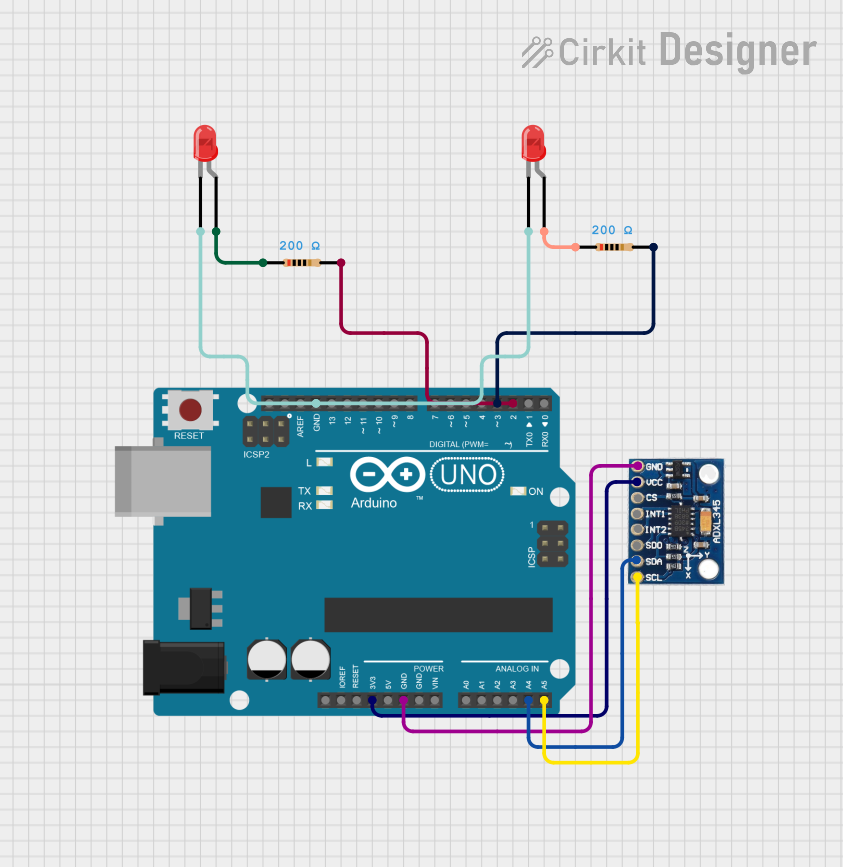
Circuit Documentation
Summary
This circuit is designed to control a digital car indicator system using an ADXL345 accelerometer and an Arduino UNO. The system detects the tilt of the car and activates the corresponding LED indicators. If the car tilts to the right, the right indicator LED turns on. If the car tilts to the left, the left indicator LED turns on. If there is no significant tilt, both LEDs remain off.
Component List
Arduino UNO
- Description: A microcontroller board based on the ATmega328P.
- Pins: UNUSED, IOREF, Reset, 3.3V, 5V, GND, Vin, A0, A1, A2, A3, A4, A5, SCL, SDA, AREF, D13, D12, D11, D10, D9, D8, D7, D6, D5, D4, D3, D2, D1, D0
ADXL345
- Description: A 3-axis accelerometer.
- Pins: GND, VCC, CS, INT1, INT2, SDO, SDA, SCL
Resistor (200 Ohms)
- Description: A resistor with a resistance of 200 Ohms.
- Pins: pin1, pin2
LED: Two Pin (red)
- Description: A red LED with two pins.
- Pins: cathode, anode
LED: Two Pin (red)
- Description: A red LED with two pins.
- Pins: cathode, anode
Resistor (200 Ohms)
- Description: A resistor with a resistance of 200 Ohms.
- Pins: pin1, pin2
Wiring Details
Arduino UNO
- 3.3V connected to VCC of ADXL345
- GND connected to GND of ADXL345
- A4 connected to SDA of ADXL345
- A5 connected to SCL of ADXL345
- GND connected to cathode of both LEDs
- D3 connected to pin2 of one Resistor (200 Ohms)
- D2 connected to pin2 of another Resistor (200 Ohms)
ADXL345
- VCC connected to 3.3V of Arduino UNO
- GND connected to GND of Arduino UNO
- SDA connected to A4 of Arduino UNO
- SCL connected to A5 of Arduino UNO
Resistor (200 Ohms)
- pin1 connected to anode of one LED
- pin2 connected to D3 of Arduino UNO
Resistor (200 Ohms)
- pin1 connected to anode of another LED
- pin2 connected to D2 of Arduino UNO
LED: Two Pin (red)
- cathode connected to GND of Arduino UNO
- anode connected to pin1 of one Resistor (200 Ohms)
LED: Two Pin (red)
- cathode connected to GND of Arduino UNO
- anode connected to pin1 of another Resistor (200 Ohms)
Code Documentation
#include <Wire.h>
#include <Adafruit_Sensor.h>
#include <Adafruit_ADXL345_U.h>

/*
 * This Arduino sketch is designed to control a digital car indicator system
 * using an ADXL345 accelerometer. The system detects the tilt of the car and
 * activates the corresponding LED indicators. If the car tilts to the right,
 * the right indicator LED turns on. If the car tilts to the left, the left
 * indicator LED turns on. If there is no significant tilt, both LEDs remain off.
 */

// Create an ADXL345 accelerometer object
Adafruit_ADXL345_Unified accel = Adafruit_ADXL345_Unified(12345);

void setup() {
  // Initialize serial communication
  Serial.begin(9600);

  // Initialize the accelerometer
  if (!accel.begin()) {
    Serial.println("No ADXL345 detected");
    while (1);
  }

  // Set the range to +/- 4G
  accel.setRange(ADXL345_RANGE_4_G);

  // Initialize the LED pins
  pinMode(2, OUTPUT); // Left Indicator
  pinMode(3, OUTPUT); // Right Indicator
}

void loop() {
  // Get the accelerometer event
  sensors_event_t event;
  accel.getEvent(&event);

  // Check the tilt of the car
  if (event.acceleration.y > 1.0) {
    // Tilted to the right
    digitalWrite(2, LOW);  // Turn off left indicator
    digitalWrite(3, HIGH); // Turn on right indicator
  } else if (event.acceleration.y < -1.0) {
    // Tilted to the left
    digitalWrite(2, HIGH); // Turn on left indicator
    digitalWrite(3, LOW);  // Turn off right indicator
  } else {
    // No significant tilt
    digitalWrite(2, LOW);  // Turn off left indicator
    digitalWrite(3, LOW);  // Turn off right indicator
  }

  // Small delay to avoid rapid switching
  delay(100);
}
This code initializes the ADXL345 accelerometer and sets up the LED pins. In the main loop, it reads the accelerometer data and determines the tilt of the car. Based on the tilt, it turns on the appropriate LED indicator.