
ESP32-Based GPS and Heart Rate Monitoring System with Battery Management
View and Edit Project In Cirkit Designer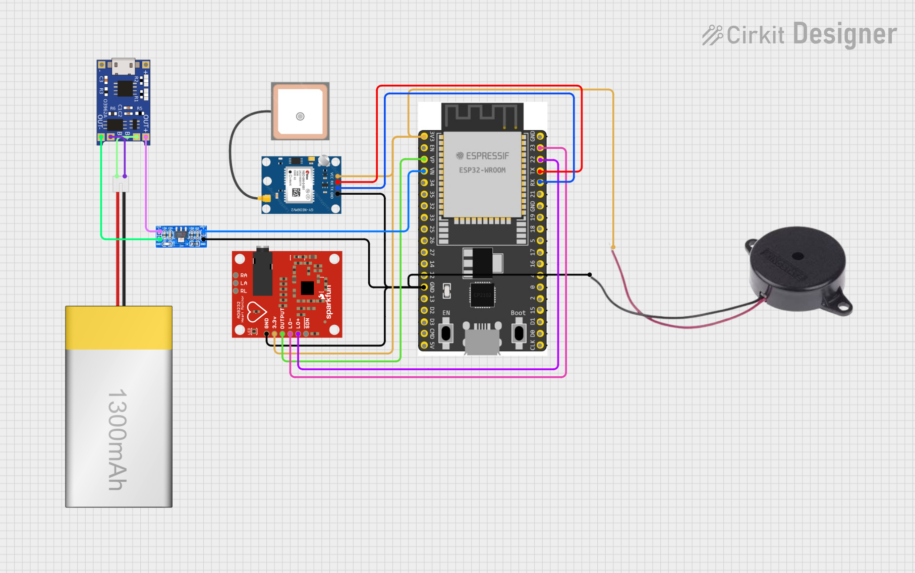
Circuit Documentation
Summary
This document provides a detailed overview of a circuit designed to monitor heart rate using an AD8232 Heart Rate Monitor, track location with a GPS NEO 6M module, and communicate data through an ESP32 Wroom Dev Kit microcontroller. The circuit is powered by a LiPoly Battery (1300mAh) managed by a TP4056 charging module and regulated by an AMS1117 voltage regulator. Additionally, a Buzzer is included for auditory feedback.
Component List
AD8232 Heart Rate Monitor
- Description: A heart rate signal monitoring module.
- Pins: GND, 3.3v, OUTPUT, LO-, LO+, SDN, RA, LA, RL
GPS NEO 6M
- Description: A GPS receiver module for location tracking.
- Pins: VCC, RX, TX, GND
ESP 32 Wroom Dev Kit
- Description: A microcontroller with Wi-Fi and Bluetooth capabilities for IoT projects.
- Pins: 3V3, EN, VP, VN, GPIO 34, GPIO 35, GPIO 32, GPIO 33, GPIO 25, GPIO 26, GPIO 27, GPIO 14, GND, GPIO 13, SD2, SD3, CMD, V5, GPIO 23, GPIO 22, TXD, RXD, GPIO 21, GPIO 19, GPIO 18, GPIO 5, GPIO 17, GPIO 16, GPIO 4, GPIO 0, GPIO 2, GPIO 15, SD1, SD0, CLK
TP4056
- Description: A lithium battery charger module with protection.
- Pins: OUT-, B-, B+, OUT+, IN-, IN+
LiPoly Battery (1300mAh)
- Description: A rechargeable lithium polymer battery.
- Pins: positive, negative
AMS1117
- Description: A voltage regulator to provide a stable 3.3V output.
- Pins: Volt Out, GND, Volt In
Buzzer
- Description: An audio signaling device.
- Pins: POSITIVE, NEGATIVE
Wiring Details
AD8232 Heart Rate Monitor
- GND connected to system ground.
- 3.3v connected to 3.3V power rail.
- OUTPUT connected to ESP32 Wroom Dev Kit pin VP.
- LO- connected to ESP32 Wroom Dev Kit pin GPIO 23.
- LO+ connected to ESP32 Wroom Dev Kit pin GPIO 22.
GPS NEO 6M
- VCC connected to 3.3V power rail.
- RX connected to ESP32 Wroom Dev Kit pin TXD.
- TX connected to ESP32 Wroom Dev Kit pin RXD.
- GND connected to system ground.
ESP 32 Wroom Dev Kit
- 3V3 connected to 3.3V power rail.
- GND connected to system ground.
- VP connected to AD8232 Heart Rate Monitor OUTPUT.
- VN connected to AMS1117 Volt Out.
- GPIO 23 connected to AD8232 Heart Rate Monitor LO-.
- GPIO 22 connected to AD8232 Heart Rate Monitor LO+.
- TXD connected to GPS NEO 6M RX.
- RXD connected to GPS NEO 6M TX.
TP4056
- OUT- connected to AMS1117 GND.
- B- connected to LiPoly Battery negative.
- B+ connected to LiPoly Battery positive.
- OUT+ connected to AMS1117 Volt In.
LiPoly Battery (1300mAh)
- positive connected to TP4056 B+.
- negative connected to TP4056 B-.
AMS1117
- Volt Out connected to ESP32 Wroom Dev Kit pin VN.
- GND connected to system ground.
- Volt In connected to TP4056 OUT+.
Buzzer
- POSITIVE connected to 3.3V power rail.
- NEGATIVE connected to system ground.
Documented Code
No code has been provided for the microcontroller. The ESP32 Wroom Dev Kit would typically be programmed to read the heart rate data from the AD8232, process GPS data from the GPS NEO 6M, and potentially communicate this information wirelessly. The code would also manage the buzzer for alerts or notifications. Since no code is available, this section will remain empty until the code is provided for documentation.