Arduino UNO Based Environmental Monitoring System with Hazard Detection
Circuit Documentation
Summary
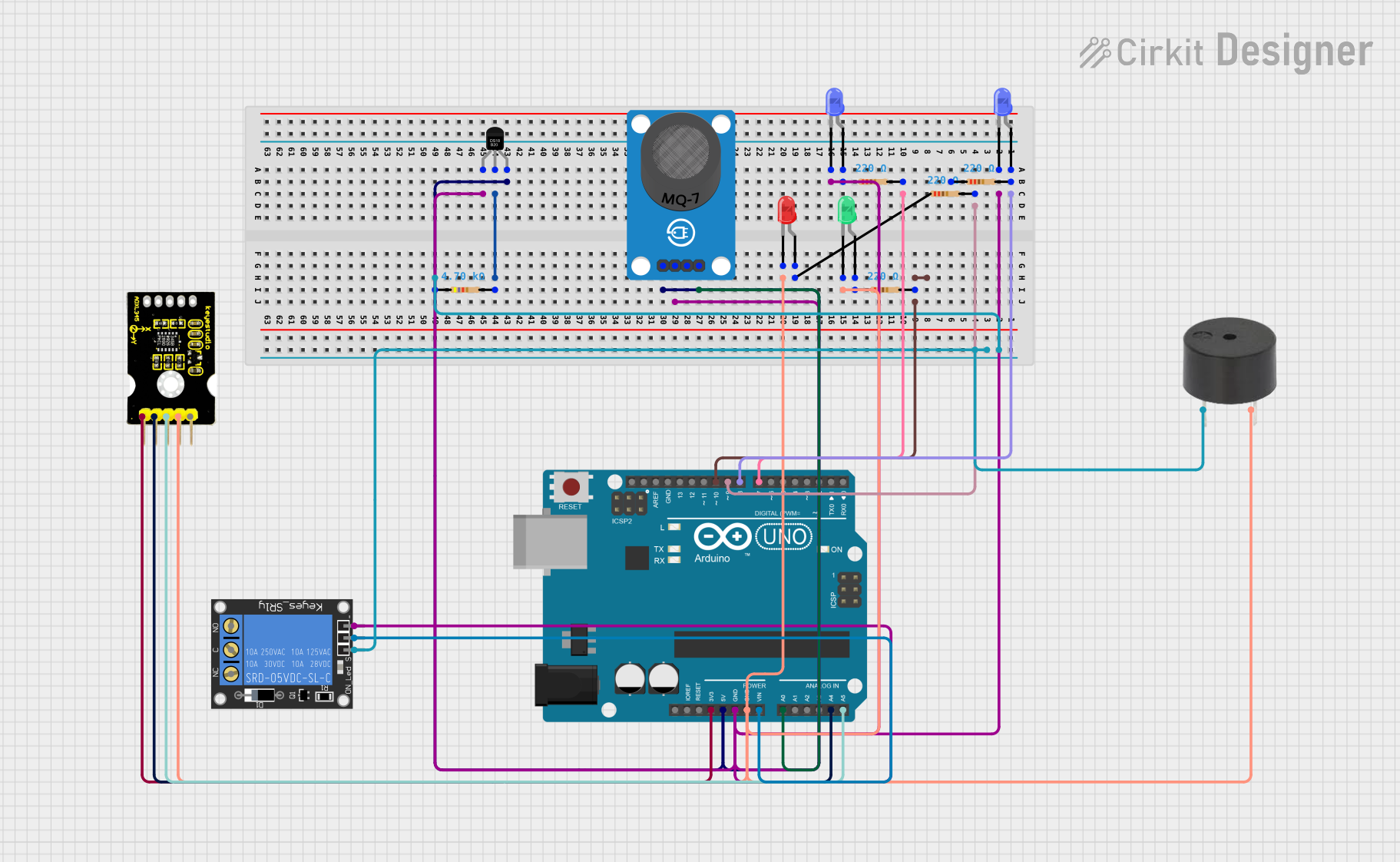
This circuit is designed to monitor environmental parameters such as temperature and smoke levels, as well as to detect motion via an accelerometer. It utilizes an Arduino UNO as the central microcontroller to process sensor data and control various outputs including a relay, a buzzer, and multiple LEDs that serve as indicators. The circuit is powered by the Arduino UNO, which supplies 3.3V and 5V to the respective components. The sensors and outputs are interfaced with the Arduino through various digital and analog pins, and the system behavior is defined by the embedded code running on the Arduino.
Component List
- Arduino UNO: A microcontroller board based on the ATmega328P, featuring digital and analog I/O pins.
- DS18B20 1-Wire Temperature Sensor: A digital temperature sensor that communicates over a 1-Wire bus.
- MQ-7 Breakout: A carbon monoxide (CO) sensor module with both analog and digital outputs.
- ADXL345 Keystudio: A digital 3-axis accelerometer for motion sensing.
- 1-Channel Relay (5V 10A): An electromechanical switch that can be controlled by a digital signal from the Arduino.
- Buzzer: An electronic sounder that can be activated to emit a tone.
- Resistor (4700 Ohms): A resistor with a resistance of 4700 Ohms.
- Resistor (220 Ohms): A resistor with a resistance of 220 Ohms, used multiple times in the circuit for current limiting purposes.
- LED (Blue): A blue light-emitting diode used as an indicator.
- LED (Red): A red light-emitting diode used as an indicator.
- LED (Green): A green light-emitting diode used as an indicator.
Wiring Details
Arduino UNO
- 3.3V: Powers the ADXL345 Keystudio.
- 5V: Powers the DS18B20 Temperature Sensor and MQ-7 Breakout.
- GND: Common ground for DS18B20, MQ-7, ADXL345, Relay, Buzzer, and LEDs.
- Vin: Supplies power to the 1-Channel Relay.
- A0: Connected to the analog output (AO) of the MQ-7 Breakout.
- A4 (SDA): I2C data line for ADXL345 Keystudio.
- A5 (SCL): I2C clock line for ADXL345 Keystudio.
- D2: Connected to the DS18B20 Temperature Sensor.
- D3: Controls the 1-Channel Relay.
- D4: Controls the Buzzer.
- D5: Controls the Warning Light (Blue LED).
- D7: Controls the Seatbelt LED (Blue LED).
- D8: Controls the Door Lock LED (Blue LED).
- D9: Controls the Hazardous Light (Red LED).
- D10: Controls the Dashboard Light (Green LED).
DS18B20 1-Wire Temperature Sensor
- VDD: Powered by 5V from Arduino UNO.
- GND: Connected to common ground.
- DQ: Data line connected to D2 on Arduino UNO through a 4700 Ohm resistor.
MQ-7 Breakout
- VCC: Powered by 5V from Arduino UNO.
- GND: Connected to common ground.
- AO: Analog output connected to A0 on Arduino UNO.
ADXL345 Keystudio
- 3.3V: Powered by 3.3V from Arduino UNO.
- SDA: I2C data line connected to A4 on Arduino UNO.
- SCL: I2C clock line connected to A5 on Arduino UNO.
- GND: Connected to common ground.
1-Channel Relay (5V 10A)
- Power: Powered by Vin from Arduino UNO.
- Ground: Connected to common ground.
- Signal: Controlled by D3 on Arduino UNO.
Buzzer
- PIN: Controlled by D4 on Arduino UNO.
- GND: Connected to common ground.
Resistor (4700 Ohms)
- Pin1: Connected to the DQ pin of the DS18B20 Temperature Sensor.
- Pin2: Connected to D2 on Arduino UNO.
Resistor (220 Ohms)
- Pin1: Connected to the anode of LEDs.
- Pin2: Connected to the respective control pins on Arduino UNO (D5, D7, D8, D9, D10).
LED (Blue, Red, Green)
- Cathode: Connected to common ground.
- Anode: Connected to the respective 220 Ohm resistors and control pins on Arduino UNO.
Documented Code
#include <OneWire.h>
#include <DallasTemperature.h>
#include <Wire.h>
#include <Adafruit_Sensor.h>
#include <Adafruit_ADXL345_U.h>

// Pin Definitions
#define TEMP_SENSOR_PIN 2
#define SMOKE_SENSOR_PIN A0
#define RELAY_PIN 3
#define BUZZER_PIN 4
#define WARNING_LIGHT_PIN 5
#define SEATBELT_LED_PIN 7
#define DOOR_LOCK_LED_PIN 8
#define HAZARDOUS_LIGHT_PIN 9 // Red LED
#define DASHBOARD_LIGHT_PIN 10 // Green LED

// Create instances for sensors
OneWire oneWire(TEMP_SENSOR_PIN);
DallasTemperature sensors(&oneWire);
Adafruit_ADXL345_Unified accel = Adafruit_ADXL345_Unified();

// Setup
void setup() {
  Serial.begin(9600);
  sensors.begin();
  accel.begin();

  pinMode(RELAY_PIN, OUTPUT);
  pinMode(BUZZER_PIN, OUTPUT);
  pinMode(WARNING_LIGHT_PIN, OUTPUT);
  pinMode(SEATBELT_LED_PIN, OUTPUT);
  pinMode(DOOR_LOCK_LED_PIN, OUTPUT);
  pinMode(HAZARDOUS_LIGHT_PIN, OUTPUT);
  pinMode(DASHBOARD_LIGHT_PIN, OUTPUT);

  digitalWrite(RELAY_PIN, LOW);
  digitalWrite(BUZZER_PIN, LOW);
  digitalWrite(WARNING_LIGHT_PIN, LOW);
  digitalWrite(SEATBELT_LED_PIN, LOW);
  digitalWrite(DOOR_LOCK_LED_PIN, LOW);
  digitalWrite(HAZARDOUS_LIGHT_PIN, LOW);
  digitalWrite(DASHBOARD_LIGHT_PIN, LOW);
}

// Main Loop
void loop() {
  // Read temperature
  sensors.requestTemperatures();
  float temperature = sensors.getTempCByIndex(0);

  // Read smoke level
  int smokeLevel = analogRead(SMOKE_SENSOR_PIN);

  // Read accelerometer data
  sensors_event_t event;
  accel.getEvent(&event);

  // Example thresholds (you can adjust these as needed)
  if (temperature > 30) {
    digitalWrite(RELAY_PIN, HIGH); // Activate relay
    digitalWrite(BUZZER_PIN, HIGH);
    digitalWrite(WARNING_LIGHT_PIN, HIGH);
    digitalWrite(SEATBELT_LED_PIN, HIGH);
    digitalWrite(DOOR_LOCK_LED_PIN, HIGH);
    digitalWrite(HAZARDOUS_LIGHT_PIN, HIGH); // Turn on Red LED
    digitalWrite(DASHBOARD_LIGHT_PIN, LOW);  // Turn off Green LED
  } else {
    digitalWrite(RELAY_PIN, LOW); // Deactivate relay
    digitalWrite(BUZZER_PIN, LOW);
    digitalWrite(WARNING_LIGHT_PIN, LOW);
    digitalWrite(SEATBELT_LED_PIN, LOW);
    digitalWrite(DOOR_LOCK_LED_PIN, LOW);
    digitalWrite(HAZARDOUS_LIGHT_PIN, LOW); // Turn off Red LED
    digitalWrite(DASHBOARD_LIGHT_PIN, HIGH); // Turn on Green LED
  }

  if (smokeLevel > 500) {
    digitalWrite(HAZARDOUS_LIGHT_PIN, HIGH); // Ensure Hazardous Light is on
    digitalWrite(DASHBOARD_LIGHT_PIN, LOW);  // Ensure Dashboard Light is off
  }

  // Print data to serial monitor
  Serial.print("Temperature: ");
  Serial.print(temperature);
  Serial.println(" C");

  Serial.print("Smoke Level: ");
  Serial.println(smokeLevel);

  Serial.print("Accelerometer X: ");
  Serial.print(event.acceleration.x);
  Serial.print(" Y: ");
  Serial.print(event.acceleration.y);
  Serial.print(" Z: ");
  Serial.println(event.acceleration.z);

  delay(2000); // Wait 2 seconds before next reading
}
This code initializes and reads from the temperature sensor, smoke sensor, and accelerometer, and controls the relay, buzzer, and LEDs based on the sensor readings. It also prints the sensor data to the serial monitor for debugging purposes.