
Arduino Nano-Based Smart Weighing System with Color Sensor and Servo Control
View and Edit Project In Cirkit Designer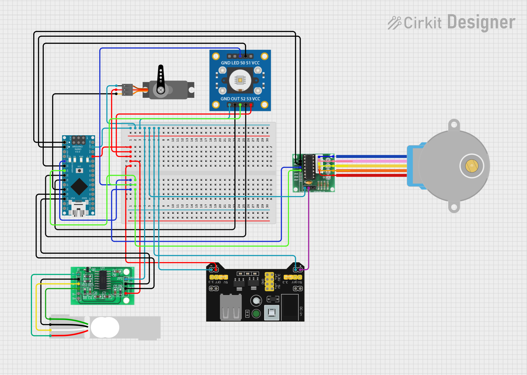
Circuit Documentation
Summary
This document provides a detailed overview of a circuit that includes an Arduino Nano, a TCS3200 color sensor, a servo motor, a breadboard power supply module, a load cell, an HX711 bridge sensor interface, a 28BYJ-48 stepper motor, and a ULN 2003 driver. The circuit is designed to interface these components for various sensing and actuation tasks.
Component List
Arduino Nano
- Description: A small, complete, and breadboard-friendly board based on the ATmega328P.
- Pins: D1/TX, D0/RX, RESET, GND, D2, D3, D4, D5, D6, D7, D8, D9, D10, D11/MOSI, D12/MISO, VIN, 5V, A7, A6, A5, A4, A3, A2, A1, A0, AREF, 3V3, D13/SCK
TCS3200
- Description: A color sensor that can detect and measure a nearly limitless range of visible colors.
- Pins: GND, OUT, S2, S3, VCC, LED, S0, S1
Servo
- Description: A small motor with a feedback mechanism to control angular position.
- Pins: GND, VCC, PWM
MB102 Breadboard Power Supply Module 3.3V/5V
- Description: A power supply module that provides 3.3V and 5V outputs.
- Pins: VCC, GND, 3.3V, 5V
Load Cell - Red/white/black/green
- Description: A sensor used to measure weight or force.
- Pins: E+, A-, E-, A+
HX711 - Bridge Sensor Interface
- Description: A precision 24-bit analog-to-digital converter (ADC) designed for weigh scales and industrial control applications to interface directly with a bridge sensor.
- Pins: E+, E-, A-, A+, B-, B+, GND - GROUND, DATA (OUT), SCK - CLOCK (IN), 3.3/3.5V Supply
28BYJ-48 Stepper Motor
- Description: A small stepper motor commonly used in various applications for precise control of angular position.
- Pins: BLUE, PINK, YELLOW, ORANGE, RED
ULN 2003
- Description: A high-voltage, high-current Darlington transistor array.
- Pins: IN1, IN2, IN3, IN4, IN5, IN6, IN7, GND, +, COIL1, COIL2, COIL3, COIL4, COIL5
Wiring Details
Arduino Nano
- D1/TX connected to ULN 2003 IN2
- D0/RX connected to ULN 2003 IN1
- D2 connected to ULN 2003 IN3 and TCS3200 S0
- D3 connected to TCS3200 S1
- D4 connected to ULN 2003 IN4 and TCS3200 S2
- D5 connected to TCS3200 S3
- D6 connected to TCS3200 OUT
- D8 connected to Servo PWM
- D9 connected to HX711 SCK - CLOCK (IN)
- D10 connected to HX711 DATA (OUT)
- 5V connected to MB102 Breadboard Power Supply Module VCC, HX711 3.3/3.5V Supply, Servo VCC, and TCS3200 VCC
- GND connected to Servo GND, TCS3200 GND, HX711 GND - GROUND, ULN 2003 GND, and MB102 Breadboard Power Supply Module GND
TCS3200
- S0 connected to Arduino Nano D2
- S1 connected to Arduino Nano D3
- S2 connected to Arduino Nano D4
- S3 connected to Arduino Nano D5
- OUT connected to Arduino Nano D6
- VCC connected to Arduino Nano 5V
- GND connected to Arduino Nano GND
Servo
- PWM connected to Arduino Nano D8
- VCC connected to Arduino Nano 5V
- GND connected to Arduino Nano GND
MB102 Breadboard Power Supply Module 3.3V/5V
- VCC connected to Arduino Nano 5V, HX711 3.3/3.5V Supply, Servo VCC, and TCS3200 VCC
- GND connected to Arduino Nano GND, Servo GND, TCS3200 GND, HX711 GND - GROUND, and ULN 2003 GND
Load Cell - Red/white/black/green
- E+ connected to HX711 E+
- A- connected to HX711 A-
- E- connected to HX711 E-
- A+ connected to HX711 A+
HX711 - Bridge Sensor Interface
- E+ connected to Load Cell E+
- A- connected to Load Cell A-
- E- connected to Load Cell E-
- A+ connected to Load Cell A+
- 3.3/3.5V Supply connected to Arduino Nano 5V
- GND - GROUND connected to Arduino Nano GND
- DATA (OUT) connected to Arduino Nano D10
- SCK - CLOCK (IN) connected to Arduino Nano D9
28BYJ-48 Stepper Motor
- BLUE connected to ULN 2003 COIL1
- PINK connected to ULN 2003 COIL2
- YELLOW connected to ULN 2003 COIL3
- ORANGE connected to ULN 2003 COIL4
- RED connected to ULN 2003 COIL5
ULN 2003
- IN1 connected to Arduino Nano D0/RX
- IN2 connected to Arduino Nano D1/TX
- IN3 connected to Arduino Nano D2 and TCS3200 S0
- IN4 connected to Arduino Nano D4 and TCS3200 S2
- GND connected to Arduino Nano GND
- + connected to MB102 Breadboard Power Supply Module VCC
- COIL1 connected to 28BYJ-48 Stepper Motor BLUE
- COIL2 connected to 28BYJ-48 Stepper Motor PINK
- COIL3 connected to 28BYJ-48 Stepper Motor YELLOW
- COIL4 connected to 28BYJ-48 Stepper Motor ORANGE
- COIL5 connected to 28BYJ-48 Stepper Motor RED
Documented Code
Arduino Nano Code (sketch.ino)
void setup() {
  // put your setup code here, to run once:

}

void loop() {
  // put your main code here, to run repeatedly:

}
Additional Documentation (documentation.txt)
This document provides a comprehensive overview of the circuit, including a detailed list of components, their wiring connections, and the code used for the Arduino Nano.