
Arduino UNO Based Ultrasonic Distance Measurement with I2C LCD Display
View and Edit Project In Cirkit Designer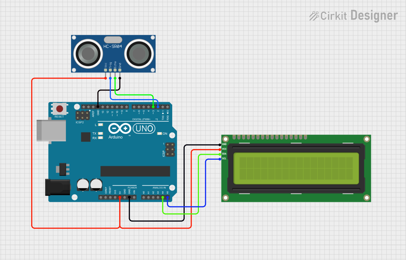
Circuit Documentation
Summary
This circuit integrates an Arduino UNO microcontroller with an I2C LCD 16x2 screen and an HC-SR04 Ultrasonic Sensor. The Arduino UNO serves as the central processing unit, controlling the LCD screen via the I2C communication protocol and interfacing with the ultrasonic sensor to potentially measure distance. The LCD screen is used to display messages, and the ultrasonic sensor can be used for proximity detection or range finding. The circuit is powered by the Arduino's 5V output, which is distributed to the other components.
Component List
Arduino UNO
- Description: A microcontroller board based on the ATmega328P. It has 14 digital input/output pins, 6 analog inputs, a 16 MHz quartz crystal, a USB connection, a power jack, an ICSP header, and a reset button.
- Purpose: Acts as the central controller for the circuit, running the embedded code to interact with the LCD screen and ultrasonic sensor.
I2C LCD 16x2 Screen
- Description: A 16-character by 2-line display that communicates with the Arduino via the I2C protocol.
- Purpose: Displays messages and information as directed by the Arduino UNO.
HC-SR04 Ultrasonic Sensor
- Description: An ultrasonic ranging module that provides 2cm to 400cm non-contact measurement functionality with a ranging accuracy that can reach up to 3mm.
- Purpose: Measures distances by emitting ultrasonic waves and detecting the reflection back from objects.
Wiring Details
Arduino UNO
- 5V: Powers the I2C LCD screen and the HC-SR04 Ultrasonic Sensor.
- GND: Common ground for the I2C LCD screen and the HC-SR04 Ultrasonic Sensor.
- A4 (SDA): Data line for I2C communication with the LCD screen.
- A5 (SCL): Clock line for I2C communication with the LCD screen.
- D2: Connected to the TRIG pin of the HC-SR04 Ultrasonic Sensor.
- D3: Connected to the ECHO pin of the HC-SR04 Ultrasonic Sensor.
I2C LCD 16x2 Screen
- SCL: Receives the clock signal from the Arduino UNO's A5 pin for I2C communication.
- SDA: Receives the data signal from the Arduino UNO's A4 pin for I2C communication.
- VCC (5V): Powered by the Arduino UNO's 5V output.
- GND: Connected to the Arduino UNO's ground.
HC-SR04 Ultrasonic Sensor
- VCC: Powered by the Arduino UNO's 5V output.
- TRIG: Sends ultrasonic pulse signals, connected to the Arduino UNO's D2 pin.
- ECHO: Receives the reflected ultrasonic signals, connected to the Arduino UNO's D3 pin.
- GND: Connected to the Arduino UNO's ground.
Documented Code
/*
 * This Arduino sketch initializes an I2C 16x2 LCD screen and displays
 * the message 'Hello' on it. The LCD is connected to the Arduino UNO
 * via the I2C interface, with SDA connected to A4 and SCL connected to A5.
 */

#include <Wire.h>
#include <LiquidCrystal_I2C.h>

// Set the LCD address to 0x27 for a 16 chars and 2 line display
LiquidCrystal_I2C lcd(0x27, 16, 2);

void setup() {
  // Initialize the LCD
  lcd.begin();
  // Turn on the backlight
  lcd.backlight();
  // Print 'Hello' to the LCD
  lcd.setCursor(0, 0);
  lcd.print("Hello");
}

void loop() {
  // Nothing to do here
}
Filename: sketch.ino
Description: The code initializes the I2C LCD screen and displays the message "Hello" on it. The setup() function is called once when the program starts and is used to initialize the LCD with the begin() method, turn on the backlight, and set the cursor to the beginning of the screen before printing "Hello". The loop() function runs continuously after setup() finishes but is left empty as there is no need for repeated actions in this simple example.